M20A-FKS COOLING FLOW SHUTTING VALVE(for Heater) INSTALLATION
PROCEDURE

 16260
1.INSTALL FLOW SHUTTING VALVE (WATER BY-PASS HOSE ASSEMBLY)
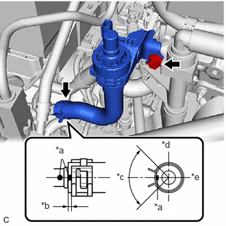
| *a | Paint Mark |
| *b | 2 to 7 mm (0.0787 to 0.276 in.) |
| *c | 120° (Tabs of Clip Installation Area) |
| *d | Upper Side of Vehicle |
| *e | Front Side of Vehicle |
Install the flow shutting valve (water by-pass hose assembly) with the bolt.
- Torque:
- 19 N*m (194 kgf*cm, 14 ft.*lbf)
Connect the flow shutting valve (water by-pass hose assembly) to the No. 1 water by-pass pipe sub-assembly and slide the clip to secure it.
- NOTICE:
- ·
Make sure to slide the flow shutting valve (water by-pass hose assembly) until it contacts the hose stopper of the No. 1 water by-pass pipe sub-assembly.
·Make sure to align the paint mark of the flow shutting valve (water by-pass hose assembly) with the paint mark of the No. 1 water by-pass pipe sub-assembly.
·Make sure that the tabs of the clip are within the area shown in the illustration.
Engage the clamp to connect the vacuum hose to the flow shutting valve (water by-pass hose assembly).
Connect the inlet heater hose connector to the flow shutting valve (water by-pass hose assembly).
- NOTICE:
-
Check that there is no damage or foreign matter on the connecting parts of the water lines.
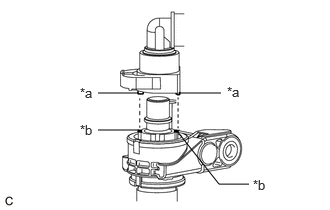
| *a | Protrusion |
| *b | Cutout |
Align the protrusions of the inlet heater hose connector with the cutouts in the flow shutting valve (water by-pass hose assembly) and securely connect the inlet heater hose connector.
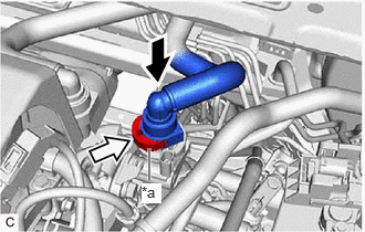
| *a | Retainer |

|
Push |

|
Push in |
Push in the retainer.
Check that the flow shutting valve (water by-pass hose assembly) and inlet heater hose connector are securely connected by pulling on them.
Connect the flow shutting valve (water by-pass hose assembly) connector.
2.ADD ENGINE COOLANT
3.INSPECT FOR COOLANT LEAK