RM33A0E
_54
Brake
_065365
BRAKE CONTROL / DYNAMIC CONTROL SYSTEMS
_0327182
VEHICLE STABILITY CONTROL SYSTEM
C
BRAKE CONTROL / DYNAMIC CONTROL SYSTEMS VEHICLE STABILITY CONTROL SYSTEM C14FE14 Steering Angle Sensor Supply Voltage Circuit Circuit Short to Ground or Open
DESCRIPTION
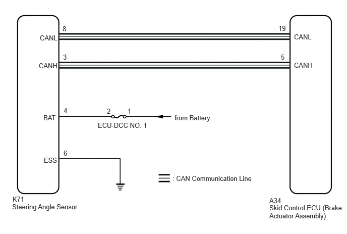
This DTC is stored when the skid control ECU (brake actuator assembly) receives a +B line open signal from the steering angle sensor.
| DTC No. | Detection Item | DTC Detection Condition | Trouble Area |
|---|---|---|---|
| C14FE14 | Steering Angle Sensor Supply Voltage Circuit Circuit Short to Ground or Open | With the +BS terminal voltage between 9.6 and 16.5 V, a steering angle sensor power supply circuit malfunction signal is received from the steering angle sensor. | ·
Wire harness or connector ·
Steering angle sensor |
WIRING DIAGRAM
6.073,0.677 6.688,0.875
0.615,0.198
10
false
CANL
0.823,0.698 1.438,0.896
0.615,0.198
10
false
CANL
0.802,1.271 1.417,1.469
0.615,0.198
10
false
CANH
6.073,1.26 6.688,1.458
0.615,0.198
10
false
CANH
0.896,2.344 1.51,2.542
0.615,0.198
10
false
BAT
2.021,2.5 3.083,2.823
1.063,0.323
10
false
ECU-DCC NO. 1
3.604,2.344 4.802,2.708
1.198,0.365
10
false
from Battery
3.563,3.594 5.708,3.948
2.146,0.354
10
false
: CAN Communication Line
0.26,4.021 0.875,4.219
0.615,0.198
10
false
K71
0.25,4.177 1.917,4.427
1.667,0.25
10
false
Steering Angle Sensor
5.563,4.052 6.177,4.25
0.615,0.198
10
false
A34
5.563,4.198 7.083,4.625
1.521,0.427
10
false
Skid Control ECU (Brake Actuator Assembly)
5.75,0.5 6.083,0.698
0.333,0.198
10
false
19
1.292,0.51 1.604,0.708
0.313,0.198
10
false
8
1.302,1.094 1.615,1.292
0.313,0.198
10
false
3
1.313,3.073 1.625,3.271
0.313,0.198
10
false
6
2.208,2.208 2.521,2.406
0.313,0.198
10
false
2
2.635,2.208 2.948,2.406
0.313,0.198
10
false
1
5.802,1.094 6.135,1.292
0.333,0.198
10
false
5
0.906,3.219 1.521,3.417
0.615,0.198
10
false
ESS
1.313,2.198 1.625,2.396
0.313,0.198
10
false
4
CAUTION / NOTICE / HINT
- NOTICE:
-
Inspect the fuses for circuits related to this system before performing the following procedure.
PROCEDURE
1.CHECK HARNESS AND CONNECTOR (POWER SOURCE TERMINAL)
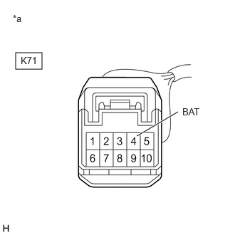
a.
0.229,0.771 0.615,1.01
0.385,0.24
2,1.99 2.604,1.635
true
0.188,0.188 0.5,0.344
0.313,0.156
10
false
*a
0.302,0.802 0.76,1
0.458,0.198
10
false
K71
2.667,1.552 3.125,1.75
0.458,0.198
10
false
BAT
| *a | Front view of wire harness connector
(to Steering Angle Sensor) |
Remove the steering wheel and column cover.
b.
Make sure that there is no looseness at the locking part and the connecting part of the connector.
- OK:
The connector is securely connected.
c.
Disconnect the K71 steering angle sensor connector.
d.
Check both the connector case and the terminals for deformation and corrosion.
- OK:
No deformation or corrosion.
e.
Measure the voltage according to the value(s) in the table below.
- Standard Voltage:
Tester Connection Condition Specified Condition K71-4 (BAT) - Body ground Always 11 to 14 V
- Result:
Proceed to OK NG
OK
REPLACE STEERING ANGLE SENSOR
NG
REPAIR OR REPLACE HARNESS OR CONNECTOR