RM33A0E
_56
Audio / Visual / Telematics
_072211
TELEMATICS
_0466472
TELEMATICS SYSTEM(for Toyota Connected Services)
J
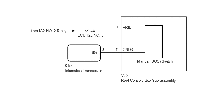
TELEMATICS TELEMATICS SYSTEM(for Toyota Connected Services) Emergency Call Switch Illumination Circuit
WIRING DIAGRAM
2.354,2.292 2.708,2.469
0.354,0.177
10
false
K156
2.333,2.479 4.219,2.781
1.885,0.302
10
false
Telematics Transceiver
4.406,2.656 4.781,2.865
0.375,0.208
10
false
V20
4.406,2.833 6.646,3.24
2.24,0.406
10
false
Roof Console Box Sub-assembly
4.208,0.896 4.469,1.115
0.26,0.219
10
false
9
4.198,1.719 4.51,1.958
0.313,0.24
10
false
12
4.458,0.906 4.844,1.083
0.385,0.177
10
false
RRID
1.104,1.031 3.01,1.313
1.906,0.281
10
false
from IG2-NO. 2 Relay
4.458,1.719 4.927,1.896
0.469,0.177
10
false
GND3
4.99,2.135 6.438,2.313
1.448,0.177
10
false
Manual (SOS) Switch
2.823,1.198 3.938,1.396
1.115,0.198
10
false
ECU-IG2 NO. 3
3.292,1.823 3.76,2
0.469,0.177
10
false
SIG-
3.708,1.708 4.021,1.948
0.313,0.24
10
false
3
CAUTION / NOTICE / HINT
- NOTICE:
-
Inspect the fuse for circuits related to this system before performing the following procedure.
PROCEDURE
1.CHECK HARNESS AND CONNECTOR (ROOF CONSOLE BOX SUB-ASSEMBLY (MANUAL (SOS) SWITCH) POWER SOURCE)
a.
Disconnect the K156 telematics transceiver connector.
b.
Disconnect the V20 roof console box sub-assembly (manual (SOS) switch) connector.
c.
Measure the voltage according to the value(s) in the table below.
- Standard Voltage:
Tester Connection Switch Condition Specified Condition V20-9 (RRID) - Body Ground Ignition switch ON 11 to 14 V
d.
Measure the resistance according to the value(s) in the table below.
- Standard Resistance:
Tester Connection Condition Specified Condition K156-3 (SIG-) - V20-12 (GND3) Always Below 1 Ω K156-3 (SIG-) or V20-12 (GND3) - Body ground Always 10 kΩ or higher
- Result:
Proceed to OK NG
OK
2.INSPECT ROOF CONSOLE BOX SUB-ASSEMBLY (MANUAL (SOS) SWITCH)
NG
REPAIR OR REPLACE HARNESS OR CONNECTOR
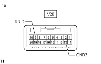
2.INSPECT ROOF CONSOLE BOX SUB-ASSEMBLY (MANUAL (SOS) SWITCH)
a.
1.51,0.354 1.927,0.604
0.417,0.25
2.24,1.469 2.344,1.885
2.344,1.885 2.552,1.885
true
0.865,0.729 1.083,0.729
1.083,0.729 1.198,1.219
true
0.073,0.094 0.354,0.333
0.281,0.24
10
false
*a
2.594,1.792 3.115,2.01
0.521,0.219
10
false
GND3
0.5,0.656 0.938,0.865
0.438,0.208
10
false
RRID
1.604,0.396 2.125,0.615
0.521,0.219
10
false
V20
| *a | Component without harness connected
(Roof Console Box Sub-assembly (Manual (SOS) Switch)) |
Remove the roof console box sub-assembly (manual (SOS) switch).
Click hereVehicle Interior>LIGHTING (INT)>PERSONAL LIGHT>REMOVAL
b.
Apply battery voltage to the connector and check that the roof console box assembly comes on.
- OK:
Measurement Condition Condition Specified Condition Battery positive (+) → V20-9 (RRID)
Battery negative (-) → V20-12 (GND3)Always Manual (SOS) switch illumination comes on
- Result:
Proceed to OK NG
OK
3.REPLACE TELEMATICS TRANSCEIVER
NG
REPLACE ROOF CONSOLE BOX SUB-ASSEMBLY (MANUAL (SOS) SWITCH)
3.REPLACE TELEMATICS TRANSCEIVER
a.
Replace the telematics transceiver with a new one.
Click hereAudio / Visual / Telematics>TELEMATICS>TELEMATICS TRANSCEIVER>REMOVAL
- Result:
Proceed to NEXT
NEXT
PERFORM REGISTRATION