PARKING BRAKE ELECTRIC PARKING BRAKE SYSTEM C060962 Electric Parking Brake Switch Signal Compare Failure
DESCRIPTION
When the electric parking brake switch is pulled, a lock request signal is sent from the skid control ECU (brake actuator assembly) to the parking brake actuator assembly. When the electric parking brake switch is pushed, a release request signal is sent from the skid control ECU (brake actuator assembly) to the parking brake actuator assembly.
| DTC No. | Detection Item | DTC Detection Condition | Trouble Area | Memory | Note |
|---|---|---|---|---|---|
| C060962 | Electric Parking Brake Switch Signal Compare Failure | ·
Open or short detected in parking brake switch circuit for 1 second or more ·
Stuck parking brake switch detected (when parked: 30 seconds, when driving: 1 second, during engine stall: 1 second) ·
Stuck parking brake switch detected 3 times in succession when being operated |
·
Electric parking brake switch assembly ·
Wire harness or connector ·
Skid control ECU (brake actuator assembly) |
DTC stored | An electric parking brake system malfunction is displayed on the combination meter assembly. |
| Vehicle Condition | |||||||
|---|---|---|---|---|---|---|---|
| Pattern 1 | Pattern 2 | Pattern 3 | Pattern 4 | Pattern 5 | Pattern 6 | ||
| Diagnosis Condition | Vehicle is stopped | - | - | ○ | - | - | - |
| Vehicle is being driven | - | - | - | ○ | - | - | |
| During initial check | - | - | - | - | ○ | - | |
| Parking brake switch is being operated | - | - | - | - | - | ○ | |
| Malfunction Status | Open detected in parking brake switch circuit | ○ | - | - | - | - | - |
| Short detected in parking brake switch circuit | - | ○ | - | - | - | - | |
| Stuck parking brake switch detected | - | - | ○ | ○ | ○ | ○ | |
| Detection Time | 1 second or more | 1 second or more | 30 seconds or more | 1 second or more | 1 second or more | - | |
| Number of Trips | 1 trip | 1 trip | 1 trip | 1 trip | 1 trip | 3 trip | |
- HINT:
-
DTC will be output when conditions for either of the patterns in the table above are met.
WIRING DIAGRAM
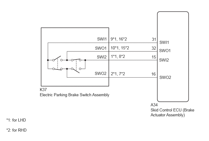
CAUTION / NOTICE / HINT
- NOTICE:
-
If the electric parking brake switch is held near the lock position but not fully in the lock position for 1 second or more, a DTC may be stored due to one of the two contacts being ON while the other is OFF. (This is not a system malfunction.)
PROCEDURE
Connect the GTS to the DLC3.
Turn the ignition switch to ON.
Enter the following menus: Chassis / Brake/EPB / Data List.
- Chassis > Brake/EPB > Data List
-
Tester Display Measurement Item Range Normal Condition Diagnostic Note EPB Switch Electric parking brake switch assembly input Neutral / Apply / Release / Unknown Neutral: Lock switch and release switch are off
Apply: Lock switch on
Release: Release switch onWhen not normal, electric parking brake switch release side system may be malfunctioning
- HINT:
-
EPB stands for electric parking brake.
- Chassis > Brake/EPB > Data List
-
Tester Display EPB Switch - 50003 435 142
Operate the electric parking brake switch assembly and check that the value of "EPB Switch" in the Data List changes between Apply and Release in accordance with the operation of the switch.
- OK:
The value of EPB Switch changes between Apply and Release in accordance with switch operation.
- Result:
Proceed to OK NG
OK
NG
Clear the DTCs.
- Chassis > Brake/EPB > Clear DTCs
- 50002 435
- Result:
Proceed to NEXT
NEXT
Check for DTCs.
- Chassis > Brake/EPB > Trouble Codes
- 50001 435
- Result:
Result Proceed to DTCs are output A DTCs are not output B
A
for LHD: Click hereBrake>BRAKE CONTROL / DYNAMIC CONTROL SYSTEMS>BRAKE ACTUATOR (for LHD)>REMOVAL
for RHD: Click hereBrake>BRAKE CONTROL / DYNAMIC CONTROL SYSTEMS>BRAKE ACTUATOR (for RHD)>REMOVAL
B
Click hereGeneral>INTRODUCTION>HOW TO TROUBLESHOOT ECU CONTROLLED SYSTEMS>HOW TO PROCEED WITH TROUBLESHOOTING
Remove the electric parking brake switch assembly.
Click hereBrake>PARKING BRAKE>ELECTRIC PARKING BRAKE SWITCH>REMOVAL
Inspect the electric parking brake switch assembly.
Click hereBrake>PARKING BRAKE>ELECTRIC PARKING BRAKE SWITCH>INSPECTION
- Result:
Proceed to OK NG
OK
NG
Disconnect the K37 electric parking brake switch assembly connector.
Disconnect the A34 skid control ECU (brake actuator assembly) connector.
Measure the resistance according to the value(s) in the table below.
- Standard Resistance:
for LHD Tester Connection Condition Specified Condition A34-31 (SWI1) - K37-9 (SWI1) Always Below 1 Ω A34-32 (SWO1) - K37-10 (SWO1) Always Below 1 Ω A34-15 (SWI2) - K37-1 (SWI2) Always Below 1 Ω A34-16 (SWO2) - K37-2 (SWO2) Always Below 1 Ω A34-31 (SWI1) or K37-9 (SWI1) - Body ground Always 10 kΩ or higher A34-32 (SWO1) or K37-10 (SWO1) - Body ground Always 10 kΩ or higher A34-15 (SWI2) or K37-1 (SWI2) - Body ground Always 10 kΩ or higher A34-16 (SWO2) or K37-2 (SWO2) - Body ground Always 10 kΩ or higher
for RHD Tester Connection Condition Specified Condition A34-31 (SWI1) - K37-16 (SWI1) Always Below 1 Ω A34-32 (SWO1) - K37-15 (SWO1) Always Below 1 Ω A34-15 (SWI2) - K37-8 (SWI2) Always Below 1 Ω A34-16 (SWO2) - K37-7 (SWO2) Always Below 1 Ω A34-31 (SWI1) or K37-16 (SWI1) - Body ground Always 10 kΩ or higher A34-32 (SWO1) or K37-15 (SWO1) - Body ground Always 10 kΩ or higher A34-15 (SWI2) or K37-8 (SWI2) - Body ground Always 10 kΩ or higher A34-16 (SWO2) or K37-7 (SWO2) - Body ground Always 10 kΩ or higher
- Result:
Proceed to OK NG
OK
NG
Clear the DTCs.
- Chassis > Brake/EPB > Clear DTCs
- 50002 435
Turn the ignition switch off.
- Result:
Proceed to NEXT
NEXT
Check for DTCs.
- Chassis > Brake/EPB > Trouble Codes
- 50001 435
- Result:
Result Proceed to DTCs are output A DTCs are not output B
A
for LHD: Click hereBrake>BRAKE CONTROL / DYNAMIC CONTROL SYSTEMS>BRAKE ACTUATOR (for LHD)>REMOVAL
for RHD: Click hereBrake>BRAKE CONTROL / DYNAMIC CONTROL SYSTEMS>BRAKE ACTUATOR (for RHD)>REMOVAL
B
Click hereGeneral>INTRODUCTION>HOW TO TROUBLESHOOT ECU CONTROLLED SYSTEMS>HOW TO PROCEED WITH TROUBLESHOOTING