Home › Steering › POWER ASSIST SYSTEMS › POWER STEERING SYSTEM
NM33C0E _55 Steering _065761 POWER ASSIST SYSTEMS _0320536 POWER STEERING SYSTEM DE DETAILS F

POWER ASSIST SYSTEMS  POWER STEERING SYSTEM  DETAILS  TORQUE SENSOR  


CONSTRUCTION


a.

A Hall IC type power steering torque sensor is used.


b.

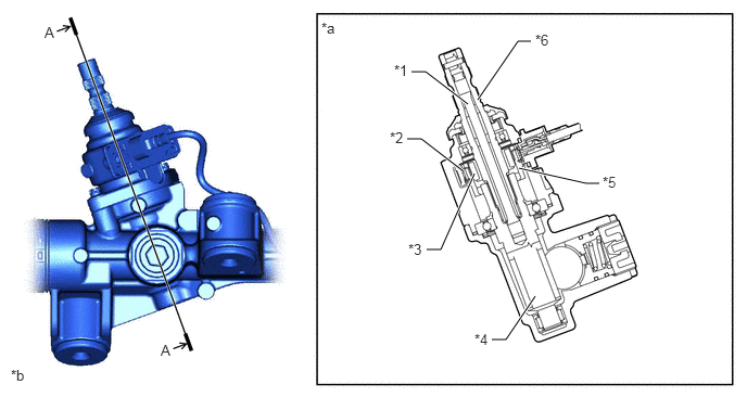
The power steering torque sensor is built into the rack and pinion power steering gear assembly. A multipole magnet is mounted on the input shaft, and a yoke is mounted on the pinion. The input and pinion are joined by the torsion bar. A magnetic convergence ring assembly is placed outside of the yoke.
X136319C01
4.719,3.26 4.854,3.26 4.854,3.26 5.135,2.844 true 3.948,0.688 4.083,0.688 4.083,0.688 4.49,1 true 3.906,1.333 4.042,1.333 4.042,1.333 4.448,1.646 true 5.094,0.396 4.969,0.396 4.969,0.396 4.583,0.958 true 4.094,2.396 4.229,2.396 4.229,2.396 4.552,1.667 true 5.75,1.76 5.625,1.76 5.625,1.76 4.979,1.615 true 3.781,0.594 4.094,0.75 0.313,0.156 10 false *1 3.74,1.24 4.052,1.396 0.313,0.156 10 false *2 3.917,2.313 4.229,2.469 0.313,0.156 10 false *3 4.552,3.177 4.865,3.333 0.313,0.156 10 false *4 5.781,1.667 6.094,1.823 0.313,0.156 10 false *5 5.135,0.302 5.448,0.458 0.313,0.156 10 false *6 3.083,0.188 3.396,0.344 0.313,0.156 10 false *a 0.104,3.521 0.417,3.677 0.313,0.156 10 false *b 0.427,0.229 0.583,0.427 0.156,0.198 10 false A 1.542,3.281 1.698,3.479 0.156,0.198 10 false A
*1 Torsion Bar *2 Magnetic Convergence Ring Assembly
*3 Multipole Magnet *4 Pinion
*5 Yoke *6 Input Shaft
*a A-A Cross Section *b The illustrations shown are examples only.


FUNCTION


a.

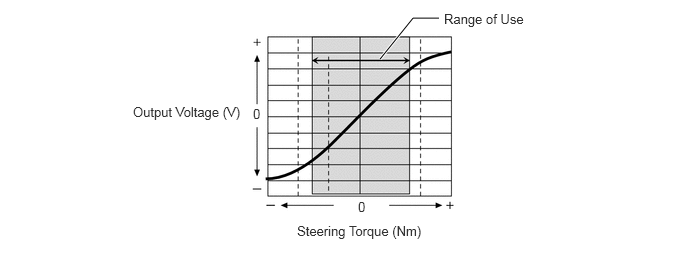
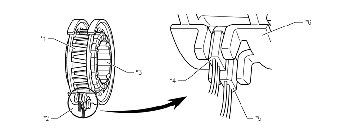
The magnetic convergence ring assembly contains 2 Hall ICs, which face opposite to each other. The system detects the steering direction in accordance with the direction of the magnetic flux that passes between the Hall ICs. Furthermore, the system detects the steering torque in accordance with the amount of change in the magnetic flux density based on the relative displacement of the multipole magnet and the yoke. The power steering ECU monitors the torque sensor signals output by the 2 Hall ICs to detect malfunctions.
X123213C03
5.573,0.75 6.281,0.469 6.281,0.469 6.438,0.469 true 4.958,1.875 5.26,2.51 5.26,2.51 5.385,2.51 true 4.49,1.271 3.948,1.708 3.948,1.708 3.792,1.708 true 2.844,1.531 2.698,1.531 2.698,1.531 2.271,1.323 true 1.594,1.031 1.146,0.823 1.146,0.823 1.021,0.823 true 1.563,2.292 1.229,2.51 1.229,2.51 1.083,2.51 true 0.854,0.74 1.167,0.896 0.313,0.156 10 false *1 0.917,2.427 1.229,2.583 0.313,0.156 10 false *2 2.885,1.448 3.198,1.604 0.313,0.156 10 false *3 3.615,1.625 3.927,1.781 0.313,0.156 10 false *4 5.427,2.427 5.74,2.583 0.313,0.156 10 false *5 6.49,0.385 6.802,0.542 0.313,0.156 10 false *6
*1 Yoke *2 Power Steering Torque Sensor
*3 Multipole Magnet *4 Hall IC 2
*5 Hall IC 1 *6 Magnetic Convergence Ring Assembly


Fluctuation of Magnetic Flux Density that Passes through Hall IC
X123214E02
3.958,0.615 4.302,0.188 4.302,0.188 4.573,0.188 true 4.625,0.115 5.563,0.292 0.938,0.177 10 false Range of Use 1.385,1.083 2.615,1.302 1.229,0.219 10 false Output Voltage (V) 2.635,1.104 2.833,1.302 0.198,0.198 10 false 0 3.729,2.073 3.927,2.271 0.198,0.198 10 false 0 3.094,2.323 4.479,2.542 1.385,0.219 10 false Steering Torque (Nm)