A25A-FXS INTAKE / EXHAUST INTAKE SYSTEM DETAILS INTAKE MANIFOLD
CONSTRUCTION
A resin intake manifold is used. This manifold has 4 small pieces integrated using vibration welding, achieving a lightweight design.
EGR delivery is integrated into the intake manifold and designed in a tournament arrangement. This allows EGR gas to be equally distributed to the cylinders while also achieving a reduced number of components and a lightweight design.
The blowby gas circuit has been integrated into the intake manifold to simplify the engine.
The insulator (No. 1 engine cover) is located between the cylinder block sub-assembly and intake manifold to improve quietness.
As the fuel delivery pipe (for high pressure side) has been made more compact by using a bolt with a smaller than usual head size for the fuel delivery pipe (for high pressure side), the port diameter of the intake manifold has been enlarged to enhance its intake ability and the power output of the engine.
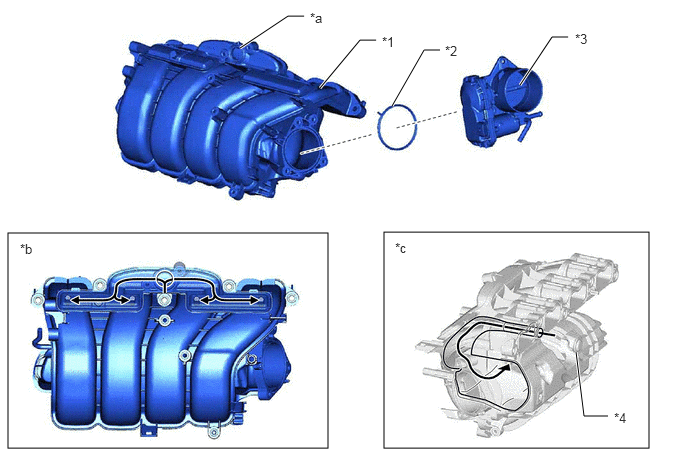
| *1 | Intake Manifold | *2 | Gasket |
| *3 | Throttle Body with Motor Assembly | *4 | Insulator (No. 1 Engine Cover) |
| *a | EGR Delivery | *b | EGR Gas Flow |
| *c | Blowby Gas Flow | - | - |