Home › Brake › BRAKE CONTROL / DYNAMIC CONTROL SYSTEMS › BRAKE CONTROL SYSTEM › 2017.09–2019.02
NM33C0E _54 Brake _067423 BRAKE CONTROL / DYNAMIC CONTROL SYSTEMS _0330428 BRAKE CONTROL SYSTEM GE GENERAL F

BRAKE CONTROL / DYNAMIC CONTROL SYSTEMS  BRAKE CONTROL SYSTEM  GENERAL  GENERAL  


OUTLINE


a.

The following brake control systems are provided: Anti-lock Brake System (ABS), Electronic Brake force Distribution (EBD), Brake Assist, Traction Control (TRC), Vehicle Stability Control (VSC), Hill-start Assist Control, Brake Hold, VSC and Cooperative Control with EPS and Secondary Collision Brake*.

*: Models with secondary collision brake system


MAIN FEATURES


a.

Electronically Controlled Brake System

i.

The electronically controlled brake system uses a sensor to detect the amount of brake pedal depression. Based on this, the skid control ECU calculates the braking force and the brake booster with master cylinder assembly, brake booster pump assembly and brake actuator assembly control the brake fluid pressure of the 4 wheels.


ii.

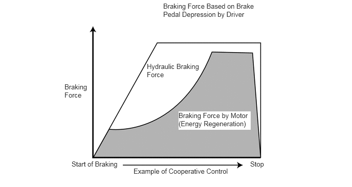
The electronically controlled brake system cooperates with the hybrid system to optimally control the brake fluid pressure and regenerative braking. This enhances the efficiency of energy regeneration and improves fuel economy.


iii.

When the system is malfunctioning, brake control continues via the use of non-malfunctioning parts. Also, when the system is not operating, the brake fluid pressure generated in the brake master cylinder by the depression of the brake pedal works as a back-up mechanism to ensure braking force.
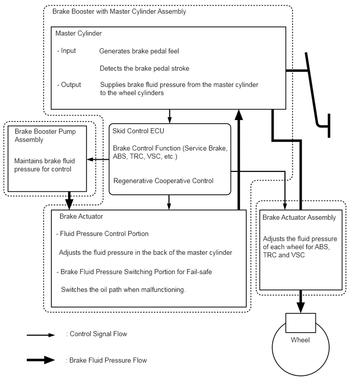
Control Outline
X131263E04
1.135,0.594 3.146,1.063 2.01,0.469 10 false Master Cylinder 1.073,0.146 4.198,0.646 3.125,0.5 10 false Brake Booster with Master Cylinder Assembly 1.167,0.948 3.177,1.417 2.01,0.469 10 false - Input 2.031,0.958 4.042,1.427 2.01,0.469 10 false Generates brake pedal feel 2.042,1.313 4.052,1.781 2.01,0.469 10 false Detects the brake pedal stroke 1.167,1.646 3.094,2 1.927,0.354 10 false - Output 2.052,1.646 5.323,2.063 3.271,0.417 10 false Supplies brake fluid pressure from the master cylinder to the wheel cylinders 2.302,2.594 3.802,2.906 1.5,0.313 10 false Skid Control ECU 2.313,2.948 4.708,3.302 2.396,0.354 10 false Brake Control Function (Service Brake, ABS, TRC, VSC, etc.) 2.323,3.615 4.719,3.969 2.396,0.354 10 false Regenerative Cooperative Control 0.302,2.604 1.604,3 1.302,0.396 10 false Brake Booster Pump Assembly 0.292,3.208 1.573,3.667 1.281,0.458 10 false Maintains brake fluid pressure for control 1.219,4.344 3.615,4.698 2.396,0.354 10 false Brake Actuator 1.146,4.698 3.542,5.052 2.396,0.354 10 false - Fluid Pressure Control Portion 1.208,5.083 5.146,5.427 3.938,0.344 10 false Adjusts the fluid pressure in the back of the master cylinder 1.25,5.844 4.344,6.146 3.094,0.302 10 false Switches the oil path when malfunctioning. 1.156,5.479 4.667,5.802 3.51,0.323 10 false - Brake Fluid Pressure Switching Portion for Fail-safe 1.354,6.75 4.448,7.052 3.094,0.302 10 false : Control Signal Flow 1.344,7.292 4.438,7.594 3.094,0.302 10 false : Brake Fluid Pressure Flow 5.375,4.365 7.031,4.75 1.656,0.385 10 false Brake Actuator Assembly 5.385,4.802 6.958,5.365 1.573,0.563 10 false Adjusts the fluid pressure of each wheel for ABS, TRC and VSC 5.958,6.875 6.625,7.115 0.667,0.24 10 false Wheel


iv.

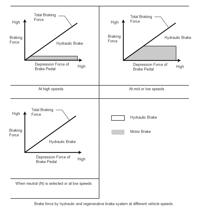
Brake control apportions brake force to the hydraulic brake system and regenerative brake system at varying vehicle speeds as follows.
X131270E01
3.323,0.042 5.219,0.573 1.896,0.531 10 false Braking Force Based on Brake Pedal Depression by Driver 1.313,1.688 1.823,2.115 0.51,0.427 10 false Braking Force 1.458,3.26 2.583,3.5 1.125,0.24 10 false Start of Braking 5.094,3.26 6.219,3.5 1.125,0.24 10 false Stop 2.719,3.406 4.875,3.635 2.156,0.229 10 false Example of Cooperative Control 3.635,2.271 5.104,2.646 1.469,0.375 10 true Braking Force by Motor (Energy Regeneration) 2.99,1.271 4.094,1.781 1.104,0.51 10 false Hydraulic Braking Force

X131271E01
2.094,0.573 2.313,0.573 2.313,0.573 2.583,0.948 false 5.542,0.604 5.76,0.604 5.76,0.604 6.031,0.979 false 2,3.948 2.219,3.948 2.219,3.948 2.49,4.323 false 4.667,4.125 5.958,4.365 1.292,0.24 10 false Hydraulic Brake 4.667,4.635 5.958,4.875 1.292,0.24 10 false Motor Brake 0.438,0.708 0.802,0.958 0.365,0.25 10 false High 3.969,0.708 4.333,0.958 0.365,0.25 10 false High 0.438,3.99 0.802,4.24 0.365,0.25 10 false High 0.344,1.26 0.844,1.698 0.5,0.438 10 false Braking Force 3.865,1.219 4.365,1.656 0.5,0.438 10 false Braking Force 0.333,4.594 0.833,5.031 0.5,0.438 10 false Braking Force 1.25,2.219 2.521,2.594 1.271,0.375 10 false Depression Force of Brake Pedal 4.771,2.229 6.042,2.604 1.271,0.375 10 false Depression Force of Brake Pedal 1.292,5.552 2.563,5.927 1.271,0.375 10 false Depression Force of Brake Pedal 2.781,2.292 3.146,2.542 0.365,0.25 10 false High 6.313,2.302 6.677,2.552 0.365,0.25 10 false High 2.781,5.625 3.146,5.875 0.365,0.25 10 false High 1.76,5 3.031,5.375 1.271,0.375 10 false Hydraulic Brake 2.021,1.469 3.292,1.844 1.271,0.375 10 false Hydraulic Brake 5.896,1.26 7.021,1.531 1.125,0.271 10 false Hydraulic Brake 1.219,0.448 2.052,0.938 0.833,0.49 10 false Total Braking Force 4.667,0.51 5.5,1 0.833,0.49 10 false Total Braking Force 1.125,3.854 1.958,4.344 0.833,0.49 10 false Total Braking Force 1.375,3.104 2.646,3.479 1.271,0.375 10 false At high speeds 4.625,3.104 6.188,3.448 1.563,0.344 10 false At mid or low speeds 0.552,6.5 3.74,6.917 3.188,0.417 10 false When neutral (N) is selected or at low speeds 1.229,7.229 6.427,7.531 5.198,0.302 10 false Brake force by hydraulic and regenerative brake system at different vehicle speeds


PRECAUTION


a.

ABS

i.

The ABS system cannot increase the performance limit of the tires. Always drive safely and be aware of the vehicle speed and distance to other vehicles.


ii.

Any non-standard components such as non-standard tires that are installed may have a negative effect on the ABS function.


iii.

When braking using ABS, the braking distance may be longer than vehicles without ABS in the following conditions:

·

When driving on a dirt road or a road covered with fresh snow

·

When using tire chains

·

When driving over a joint in the road surface

·

When driving on a rough road such as an unpaved or stone-paved road


b.

Brake Assist

i.

Brake assist cannot increase the performance limit of the fundamental brake system. Always drive safely and be aware of the vehicle speed and distance to other vehicles.


c.

TRC, VSC

i.

The TRC and VSC systems ensure traction and vehicle stability. Do not disable the TRC or VSC functions unless necessary.


ii.

The TRC and VSC systems cannot increase the performance limit of the tires. Always drive the vehicle carefully in conditions in which drive wheel traction or vehicle stability may be lost.


d.

Hill-start Assist Control

i.

Hill-start assist control is not intended to keep the vehicle stationary on a hill for a prolonged period. As hill-start assist control only prevents the vehicle from rolling backwards for 2 seconds after the brake pedal is released, perform start-off within this period.


ii.

When hill-start assist control is operating and the power switch is turned off, hill-start assist control will be canceled without warning.


iii.

Hill-start assist control prevents the vehicle from rolling backwards by controlling the brake force to the 4 wheels. However, the vehicle may not remain stationary when on an extremely steep slope or a low friction surface such as ice.


e.

Brake Hold

i.

Brake hold is not intended to keep the vehicle parked for a prolonged period, such as the parking brake is designed to do.


ii.

When brake hold is operating and the power switch (push start switch) is turned off, hill-start assist control will be canceled without warning.


iii.

If brake hold does not operate even though the vehicle is stopped, firmly depress the brake pedal. If brake hold still does not operate, check the operating conditions.


iv.

It may not be possible for brake hold to keep the vehicle stationary on a steep or slippery road.