Home › Engine / Hybrid System › A25A-FXS (ENGINE CONTROL) › RELAY
RM33C0E _51 Engine / Hybrid System _065419 A25A-FXS ENGINE CONTROL _0326955 RELAY G

A25A-FXS ENGINE CONTROL  RELAY  ON-VEHICLE INSPECTION  


PROCEDURE

Hide 89561B 1.INSPECT NO. 1 ELECTRONIC FUEL INJECTION MAIN RELAY (EFI-MAIN NO. 1)
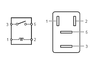
a.
A273391N01
2.667,0.74 2.927,0.74 true 2.531,1.125 2.948,1.125 true 2.531,1.625 2.948,1.625 true 1.708,0.74 1.969,0.74 true 0.229,1.313 0.385,1.51 0.156,0.198 10 1 1.188,1.313 1.344,1.51 0.156,0.198 10 2 0.219,0.781 0.375,0.979 0.156,0.198 10 3 1.188,0.771 1.344,0.969 0.156,0.198 10 5 3,1.052 3.156,1.25 0.156,0.198 10 5 1.604,0.667 1.76,0.865 0.156,0.198 10 1 2.99,0.667 3.146,0.865 0.156,0.198 10 2 3,1.552 3.156,1.75 0.156,0.198 10 3

Measure the resistance according to the value(s) in the table below.

Standard Resistance:
Tester Connection Condition Specified Condition
3 - 5 Auxiliary battery voltage not applied between terminals 1 and 2 10 kΩ or higher
Auxiliary battery voltage applied between terminals 1 and 2 Below 1 Ω


If the result is not as specified, replace the No. 1 electronic fuel injection main relay (EFI-MAIN NO. 1).


Hide 89561C 2.INSPECT NO. 2 ELECTRONIC FUEL INJECTION MAIN RELAY (EFI-MAIN NO. 2)

a.
A273391N01
2.667,0.74 2.927,0.74 true 2.531,1.125 2.948,1.125 true 2.531,1.625 2.948,1.625 true 1.708,0.74 1.969,0.74 true 0.229,1.313 0.385,1.51 0.156,0.198 10 1 1.188,1.313 1.344,1.51 0.156,0.198 10 2 0.219,0.781 0.375,0.979 0.156,0.198 10 3 1.188,0.771 1.344,0.969 0.156,0.198 10 5 3,1.052 3.156,1.25 0.156,0.198 10 5 1.604,0.667 1.76,0.865 0.156,0.198 10 1 2.99,0.667 3.146,0.865 0.156,0.198 10 2 3,1.552 3.156,1.75 0.156,0.198 10 3

Measure the resistance according to the value(s) in the table below.

Standard Resistance:
Tester Connection Condition Specified Condition
3 - 5 Auxiliary battery voltage not applied between terminals 1 and 2 10 kΩ or higher
Auxiliary battery voltage applied between terminals 1 and 2 Below 1 Ω


If the result is not as specified, replace the No. 2 electronic fuel injection main relay (EFI-MAIN NO. 2).


Hide 89561E 3.INSPECT NO. 3 ELECTRONIC FUEL INJECTION MAIN RELAY (EFI-MAIN NO. 3)

a.
A273391N01
2.667,0.74 2.927,0.74 true 2.531,1.125 2.948,1.125 true 2.531,1.625 2.948,1.625 true 1.708,0.74 1.969,0.74 true 0.229,1.313 0.385,1.51 0.156,0.198 10 1 1.188,1.313 1.344,1.51 0.156,0.198 10 2 0.219,0.781 0.375,0.979 0.156,0.198 10 3 1.188,0.771 1.344,0.969 0.156,0.198 10 5 3,1.052 3.156,1.25 0.156,0.198 10 5 1.604,0.667 1.76,0.865 0.156,0.198 10 1 2.99,0.667 3.146,0.865 0.156,0.198 10 2 3,1.552 3.156,1.75 0.156,0.198 10 3

Measure the resistance according to the value(s) in the table below.

Standard Resistance:
Tester Connection Condition Specified Condition
3 - 5 Auxiliary battery voltage not applied between terminals 1 and 2 10 kΩ or higher
Auxiliary battery voltage applied between terminals 1 and 2 Below 1 Ω


If the result is not as specified, replace the No. 3 electronic fuel injection main relay (EFI-MAIN NO. 3).


Hide 89870B 4.INSPECT ELECTRONIC DRIVER UNIT RELAY (D INJ)

a.
A273391N01
2.667,0.74 2.927,0.74 true 2.531,1.125 2.948,1.125 true 2.531,1.625 2.948,1.625 true 1.708,0.74 1.969,0.74 true 0.229,1.313 0.385,1.51 0.156,0.198 10 1 1.188,1.313 1.344,1.51 0.156,0.198 10 2 0.219,0.781 0.375,0.979 0.156,0.198 10 3 1.188,0.771 1.344,0.969 0.156,0.198 10 5 3,1.052 3.156,1.25 0.156,0.198 10 5 1.604,0.667 1.76,0.865 0.156,0.198 10 1 2.99,0.667 3.146,0.865 0.156,0.198 10 2 3,1.552 3.156,1.75 0.156,0.198 10 3

Measure the resistance according to the value(s) in the table below.

Standard Resistance:
Tester Connection Condition Specified Condition
3 - 5 Auxiliary battery voltage not applied between terminals 1 and 2 10 kΩ or higher
Auxiliary battery voltage applied between terminals 1 and 2 Below 1 Ω


If the result is not as specified, replace the electronic driver unit relay (D INJ).


Hide 85912K 5.INSPECT VVT RELAY (VVT)

a.
A273391N01
2.667,0.74 2.927,0.74 true 2.531,1.125 2.948,1.125 true 2.531,1.625 2.948,1.625 true 1.708,0.74 1.969,0.74 true 0.229,1.313 0.385,1.51 0.156,0.198 10 1 1.188,1.313 1.344,1.51 0.156,0.198 10 2 0.219,0.781 0.375,0.979 0.156,0.198 10 3 1.188,0.771 1.344,0.969 0.156,0.198 10 5 3,1.052 3.156,1.25 0.156,0.198 10 5 1.604,0.667 1.76,0.865 0.156,0.198 10 1 2.99,0.667 3.146,0.865 0.156,0.198 10 2 3,1.552 3.156,1.75 0.156,0.198 10 3

Measure the resistance according to the value(s) in the table below.

Standard Resistance:
Tester Connection Condition Specified Condition
3 - 5 Auxiliary battery voltage not applied between terminals 1 and 2 10 kΩ or higher
Auxiliary battery voltage applied between terminals 1 and 2 Below 1 Ω


If the result is not as specified, replace the VVT relay (VVT).


Hide 28371C 6.INSPECT NO. 2 IGNITION RELAY (IG2 NO. 1)

a.
A273391N01
2.667,0.74 2.927,0.74 true 2.531,1.125 2.948,1.125 true 2.531,1.625 2.948,1.625 true 1.708,0.74 1.969,0.74 true 0.229,1.313 0.385,1.51 0.156,0.198 10 1 1.188,1.313 1.344,1.51 0.156,0.198 10 2 0.219,0.781 0.375,0.979 0.156,0.198 10 3 1.188,0.771 1.344,0.969 0.156,0.198 10 5 3,1.052 3.156,1.25 0.156,0.198 10 5 1.604,0.667 1.76,0.865 0.156,0.198 10 1 2.99,0.667 3.146,0.865 0.156,0.198 10 2 3,1.552 3.156,1.75 0.156,0.198 10 3

Measure the resistance according to the value(s) in the table below.

Standard Resistance:
Tester Connection Condition Specified Condition
3 - 5 Auxiliary battery voltage not applied between terminals 1 and 2 10 kΩ or higher
Auxiliary battery voltage applied between terminals 1 and 2 Below 1 Ω


If the result is not as specified, replace the No. 2 ignition relay (IG2 NO. 1).