INTERIOR PANELS / TRIM INSTRUMENT PANEL SAFETY PAD REASSEMBLY
PROCEDURE

 69550A
1.INSTALL GLOVE COMPARTMENT DOOR LOCK CYLINDER ASSEMBLY
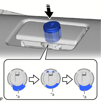
| *a | Cylinder Lock Plate |

|
Install in this Direction |
With the cylinder lock plate pressed, insert the glove compartment door lock cylinder assembly into the glove compartment door lever to install it as shown in the illustration.
- NOTICE:
-
After installing the glove compartment door lock cylinder assembly, lift the glove compartment door lever and confirm that the cylinder lock plate is correctly protruding and that the glove compartment door lock cylinder assembly does not move even when pushed from the rear.
2.INSTALL INSTRUMENT PANEL CUSHION
Clean the instrument panel safety pad sub-assembly surface.
Remove any remaining double-sided tape from the instrument panel safety pad sub-assembly.
Wipe off any tape adhesive residue with cleaner.
Remove the release paper from a new instrument panel cushion.
- HINT:
-
After removing the release paper, keep the exposed adhesive free from foreign matter.
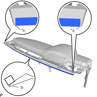
| *a | Edge of Curved Surface |
| *b | Outline |
Install the instrument panel cushion as shown in the illustration.
82144
3.INSTALL NO. 4 INSTRUMENT PANEL WIRE (w/ Ion Generator)
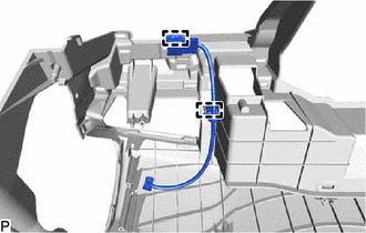
Engage the 2 clamps to install the No. 4 instrument panel wire.
4.INSTALL ION GENERATOR WITH BRACKET (w/ Ion Generator)
87201N
5.INSTALL AIR DUCT SUB-ASSEMBLY (w/ Ion Generator)
for RHD:
Click hereVehicle Interior>HEATING / AIR CONDITIONING>ION GENERATOR>INSTALLATION
86101
6.INSTALL ANTENNA CORD SUB-ASSEMBLY (for LHD)
86101
7.INSTALL ANTENNA CORD SUB-ASSEMBLY (for RHD)
55328
8.INSTALL NO. 1 INSTRUMENT PANEL PIN
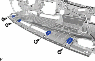
Install the 4 No. 1 instrument panel pins with the 4 screws <E>.
9.INSTALL INSTRUMENT PANEL HOLE COVER (w/ Headup Display)
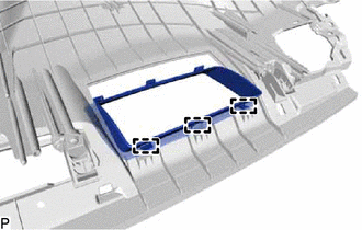
Engage the 3 guides.
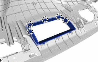
Engage the 5 claws to install the instrument panel hole cover.
55981
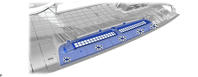
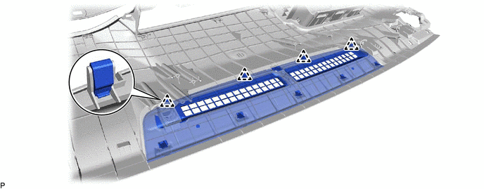
10.INSTALL NO. 1 DEFROSTER NOZZLE GARNISH
Engage the 5 guides.
Engage the 4 clips to install the No. 1 defroster nozzle garnish.
83107A
11.INSTALL NO. 1 METER BRACKET SUB-ASSEMBLY
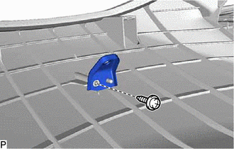
Install the No. 1 meter bracket sub-assembly with the screw <E>.
83107B
12.INSTALL NO. 2 METER BRACKET SUB-ASSEMBLY (w/ Headup Display)
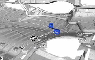
Install the No. 2 meter bracket sub-assembly with the screw <E>.
82143
13.INSTALL NO. 3 INSTRUMENT PANEL WIRE
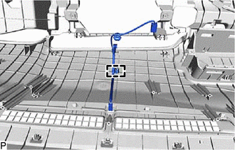
Engage the clamp to install the No. 3 instrument panel wire.
55660
14.INSTALL NO. 2 INSTRUMENT PANEL REGISTER ASSEMBLY
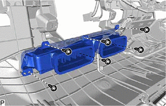
Install the No. 2 instrument panel register assembly with the 6 screws <E>.
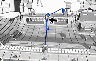
Connect the connector.
89120A
15.INSTALL AUTOMATIC LIGHT CONTROL SENSOR
55085
16.INSTALL NO. 2 HEATER TO REGISTER DUCT SUB-ASSEMBLY
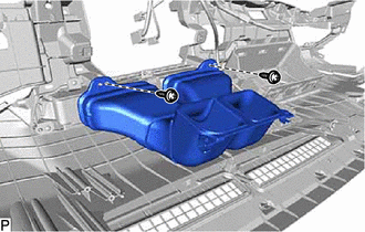
Install the No. 2 heater to register duct sub-assembly with the 2 screws <E>.
17.INSTALL NAVIGATION ANTENNA ASSEMBLY WITH BRACKET (w/ Navigation Antenna)
86101H
18.INSTALL ANTENNA CORD SUB-ASSEMBLY (w/ Navigation Antenna)
55086
19.INSTALL NO. 3 HEATER TO REGISTER DUCT SUB-ASSEMBLY
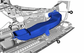
Install the No. 3 heater to register duct sub-assembly with the 3 screws <E>.
55084E
20.INSTALL NO. 1 HEATER TO REGISTER DUCT SUB-ASSEMBLY
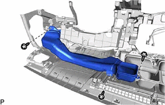
Install the No. 1 heater to register duct sub-assembly with the 3 screws <E>.
83108
21.INSTALL METER MIRROR SUB-ASSEMBLY (w/ Headup Display)
55950G
22.INSTALL DEFROSTER NOZZLE ASSEMBLY
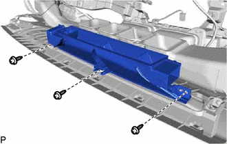
Install the defroster nozzle assembly with the 3 screws <E>.
55972C
23.INSTALL NO. 2 SIDE DEFROSTER NOZZLE DUCT
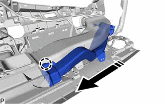
|
|
Install in this Direction |
Engage the claw as shown in the illustration.
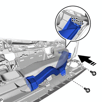
|
|
Install in this Direction |
Engage the 2 guides as shown in the illustration.
Install the No. 2 side defroster nozzle duct with the 2 screws <E>.
55971C
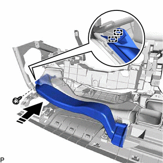
24.INSTALL NO. 1 SIDE DEFROSTER NOZZLE DUCT
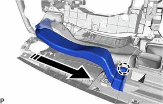
|
|
Install in this Direction |
Engage the claw as shown in the illustration.
|
|
Install in this Direction |
Engage the 2 guides as shown in the illustration.
Install the No. 1 side defroster nozzle duct with the screw <E>.
73960A
25.INSTALL INSTRUMENT PANEL PASSENGER AIRBAG ASSEMBLY
w/o Occupant Classification System:
Click hereVehicle Interior>SUPPLEMENTAL RESTRAINT SYSTEMS>FRONT PASSENGER AIRBAG ASSEMBLY>INSTALLATION
w/ Occupant Classification System:
Click hereVehicle Interior>SUPPLEMENTAL RESTRAINT SYSTEMS>FRONT PASSENGER AIRBAG ASSEMBLY>INSTALLATION