Home › Audio / Visual / Telematics › PARK ASSIST / MONITORING › TOYOTA PARKING ASSIST-SENSOR SYSTEM (w/ Parking Support Brake System) › 2019.02–2021.02
RM33C0E _56 Audio / Visual / Telematics _065452 PARK ASSIST / MONITORING _0387692 TOYOTA PARKING ASSIST-SENSOR SYSTEM(w/ Parking Support Brake System) C

PARK ASSIST / MONITORING  TOYOTA PARKING ASSIST-SENSOR SYSTEM(w/ Parking Support Brake System)  C1AED  Rear Sensor Communication Malfunction  


DESCRIPTION

This DTC is stored when there is an open or short circuit in the communication line between the rear sensors and the ECU, or when there is a malfunction in a rear sensor.

DTC No. Detection Item DTC Detection Condition Trouble Area
C1AED Rear Sensor Communication Malfunction An open or short circuit in the communication line between the rear sensors and ECU or a malfunction in a rear sensor during initialization mode after the power switch is turned on (IG).
·

Rear ultrasonic sensor circuit

·

Harness or connector

·

Clearance warning ECU assembly


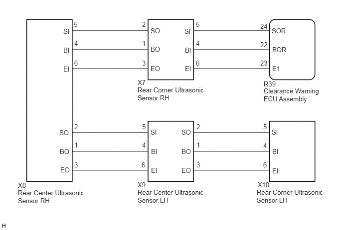
WIRING DIAGRAM

E410481E11
2.875,3.948 4.344,4.354 1.469,0.406 10 false Rear Center Ultrasonic Sensor LH 5.365,3.948 6.792,4.333 1.427,0.385 10 false Rear Corner Ultrasonic Sensor LH 0.375,3.958 1.865,4.375 1.49,0.417 10 false Rear Center Ultrasonic Sensor RH 3.865,0.969 4.031,1.25 0.167,0.281 10 false BI 3.865,1.354 4.063,1.604 0.198,0.25 10 false EI 3.854,0.573 4.042,0.854 0.188,0.281 10 false SI 3.146,0.948 3.427,1.208 0.281,0.26 10 false BO 3.146,1.354 3.417,1.594 0.271,0.24 10 false EO 3.146,0.563 3.417,0.833 0.271,0.271 10 false SO 1.323,0.969 1.531,1.208 0.208,0.24 10 false BI 1.323,1.365 1.521,1.604 0.198,0.24 10 false EI 1.323,0.573 1.521,0.813 0.198,0.24 10 false SI 1.25,3.094 1.49,3.333 0.24,0.24 10 false BO 1.26,3.479 1.542,3.771 0.281,0.292 10 false EO 1.24,2.698 1.458,2.969 0.219,0.271 10 false SO 5.688,3.5 5.917,3.76 0.229,0.26 10 false EI 5.677,2.688 5.896,2.906 0.219,0.219 10 false SI 5.688,3.094 5.885,3.323 0.198,0.229 10 false BI 4.094,0.427 4.25,0.583 0.156,0.156 10 false 5 2.969,0.823 3.073,0.979 0.104,0.156 10 false 1 2.969,0.427 3.073,0.583 0.104,0.156 10 false 2 4.094,1.24 4.25,1.396 0.156,0.156 10 false 6 4.094,0.823 4.25,0.979 0.156,0.156 10 false 4 2.969,1.24 3.073,1.396 0.104,0.156 10 false 3 1.542,0.427 1.698,0.583 0.156,0.156 10 false 5 1.552,2.958 1.708,3.115 0.156,0.156 10 false 1 1.552,2.573 1.708,2.729 0.156,0.156 10 false 2 1.552,1.24 1.708,1.396 0.156,0.156 10 false 6 1.552,0.823 1.708,0.979 0.156,0.156 10 false 4 1.552,3.375 1.708,3.531 0.156,0.156 10 false 3 5.5,2.573 5.604,2.729 0.104,0.156 10 false 5 5.5,3.375 5.604,3.531 0.104,0.156 10 false 6 5.5,2.969 5.604,3.125 0.104,0.156 10 false 4 3.156,3.094 3.354,3.354 0.198,0.26 10 false BI 3.156,3.49 3.333,3.74 0.177,0.25 10 false EI 3.146,2.688 3.333,3 0.188,0.313 10 false SI 3.792,3.094 4.083,3.333 0.292,0.24 10 false BO 3.792,3.49 4.052,3.771 0.26,0.281 10 false EO 3.792,2.688 4.094,2.906 0.302,0.219 10 false SO 4.104,2.573 4.26,2.729 0.156,0.156 10 false 2 2.969,2.958 3.073,3.115 0.104,0.156 10 false 4 2.969,2.573 3.073,2.729 0.104,0.156 10 false 5 4.104,3.375 4.26,3.531 0.156,0.156 10 false 3 4.104,2.958 4.26,3.115 0.156,0.156 10 false 1 2.958,3.375 3.063,3.531 0.104,0.156 10 false 6 2.875,3.792 3.135,3.958 0.26,0.167 10 false X9 0.375,3.802 0.667,3.969 0.292,0.167 10 false X8 5.51,1.823 6.74,2.156 1.229,0.333 10 false Clearance Warning ECU Assembly 5.688,0.958 6.104,1.208 0.417,0.25 10 false BOR 5.688,1.354 6.104,1.635 0.417,0.281 10 false E1 5.677,0.563 6.135,0.854 0.458,0.292 10 false SOR 5.438,0.854 5.75,1.063 0.313,0.208 10 false 22 5.438,1.24 5.615,1.396 0.177,0.156 10 false 23 5.438,0.469 5.823,0.625 0.385,0.156 10 false 24 5.51,1.677 5.802,1.844 0.292,0.167 10 false R39 5.385,3.792 5.656,3.958 0.271,0.167 10 false X10 2.875,1.802 4.333,2.198 1.458,0.396 10 false Rear Corner Ultrasonic Sensor RH 2.875,1.646 3.135,1.813 0.26,0.167 10 false X7

PROCEDURE

1.INITIALIZE REAR CENTER ULTRASONIC SENSOR AND REAR CORNER ULTRASONIC SENSOR
a.

Initialize the rear center ultrasonic sensor and rear corner ultrasonic sensor.

Click hereAudio / Visual / Telematics>PARK ASSIST / MONITORING>PARKING SUPPORT BRAKE SYSTEM>CALIBRATION


Result:
Proceed to
NEXT


NEXT

2.CHECK DTC OUTPUT (C1AED)
a.

Check for DTCs.

Body Electrical > IPA/ICS/Clearance Sonar > Trouble Codes
50001 170

b.

Clear the DTCs.

Body Electrical > IPA/ICS/Clearance Sonar > Clear DTCs
50002 170

c.

Recheck for DTCs.

Body Electrical > IPA/ICS/Clearance Sonar > Trouble Codes
50001 170

Result:
Result Proceed to
DTC C1AED is output A
No DTCs are output B


A

3.CHECK HARNESS AND CONNECTOR (CLEARANCE WARNING ECU ASSEMBLY - REAR CORNER ULTRASONIC SENSOR RH)

B

3.CHECK HARNESS AND CONNECTOR (CLEARANCE WARNING ECU ASSEMBLY - REAR CORNER ULTRASONIC SENSOR RH)
a.

Disconnect the R39 clearance warning ECU assembly connector.


b.

Disconnect the X7 rear corner ultrasonic sensor RH.


c.

Measure the resistance according to the value(s) in the table below.

Standard Resistance:
Tester Connection Condition Specified Condition
R39-22 (BOR) - X7-4 (BI) Always Below 1 Ω
R39-24 (SOR) - X7-5 (SI) Always Below 1 Ω
R39-23 (E1) - X7-6 (EI) Always Below 1 Ω
R39-22 (BOR) or X7-4 (BI) - Body ground Always 10 kΩ or higher
R39-24 (SOR) or X7-5 (SI) - Body ground Always 10 kΩ or higher
R39-23 (E1) or X7-6 (EI) - Body ground Always 10 kΩ or higher


Result:
Proceed to
OK
NG


OK

4.CHECK HARNESS AND CONNECTOR (REAR CORNER ULTRASONIC SENSOR RH - REAR CENTER ULTRASONIC SENSOR RH)

NG

REPAIR OR REPLACE HARNESS OR CONNECTOR

4.CHECK HARNESS AND CONNECTOR (REAR CORNER ULTRASONIC SENSOR RH - REAR CENTER ULTRASONIC SENSOR RH)
a.

Disconnect the X8 rear center ultrasonic sensor RH.


b.

Measure the resistance according to the value(s) in the table below.

Standard Resistance:
Tester Connection Condition Specified Condition
X7-1 (BO) - X8-4 (BI) Always Below 1 Ω
X7-2 (SO) - X8-5 (SI) Always Below 1 Ω
X7-3 (EO) - X8-6 (EI) Always Below 1 Ω
X7-1 (BO) or X8-4 (BI) - Body ground Always 10 kΩ or higher
X7-2 (SO) or X8-5 (SI) - Body ground Always 10 kΩ or higher
X7-3 (EO) or X8-6 (EI) - Body ground Always 10 kΩ or higher


Result:
Proceed to
OK
NG


OK

5.CHECK HARNESS AND CONNECTOR (REAR CENTER ULTRASONIC SENSOR RH - REAR CENTER ULTRASONIC SENSOR LH)

NG

REPAIR OR REPLACE HARNESS OR CONNECTOR

5.CHECK HARNESS AND CONNECTOR (REAR CENTER ULTRASONIC SENSOR RH - REAR CENTER ULTRASONIC SENSOR LH)
a.

Disconnect the X9 rear center ultrasonic sensor LH.


b.

Measure the resistance according to the value(s) in the table below.

Standard Resistance:
Tester Connection Condition Specified Condition
X8-1 (BO) - X9-4 (BI) Always Below 1 Ω
X8-2 (SO) - X9-5 (SI) Always Below 1 Ω
X8-3 (EO) - X9-6 (EI) Always Below 1 Ω
X8-1 (BO) or X9-4 (BI) - Body ground Always 10 kΩ or higher
X8-2 (SO) or X9-5 (SI) - Body ground Always 10 kΩ or higher
X8-3 (EO) or X9-6 (EI) - Body ground Always 10 kΩ or higher


Result:
Proceed to
OK
NG


OK

6.CHECK HARNESS AND CONNECTOR (REAR CENTER ULTRASONIC SENSOR LH - REAR CORNER ULTRASONIC SENSOR LH)

NG

REPAIR OR REPLACE HARNESS OR CONNECTOR

6.CHECK HARNESS AND CONNECTOR (REAR CENTER ULTRASONIC SENSOR LH - REAR CORNER ULTRASONIC SENSOR LH)
a.

Disconnect the X10 rear corner ultrasonic sensor LH.


b.

Measure the resistance according to the value(s) in the table below.

Standard Resistance:
Tester Connection Condition Specified Condition
X9-1 (BO) - X10-4 (BI) Always Below 1 Ω
X9-2 (SO) - X10-5 (SI) Always Below 1 Ω
X9-3 (EO) - X10-6 (EI) Always Below 1 Ω
X9-1 (BO) or X10-4 (BI) - Body ground Always 10 kΩ or higher
X9-2 (SO) or X10-5 (SI) - Body ground Always 10 kΩ or higher
X9-3 (EO) or X10-6 (EI) - Body ground Always 10 kΩ or higher


Result:
Proceed to
OK
NG


OK

7.INSPECT REAR CORNER ULTRASONIC SENSOR RH

NG

REPAIR OR REPLACE HARNESS OR CONNECTOR

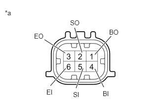
7.INSPECT REAR CORNER ULTRASONIC SENSOR RH
a.
E332147C01
0.938,0.833 1.375,1.115 true 1.573,0.583 1.729,1.104 true 2.344,0.76 2,1.146 true 2.188,1.833 2,1.448 true 1.604,1.854 1.75,1.438 true 1.063,1.802 1.385,1.438 true 0.104,0.188 0.417,0.344 0.313,0.156 10 false *a 0.719,0.677 1.031,0.833 0.313,0.156 10 false EO 1.479,0.396 1.792,0.552 0.313,0.156 10 false SO 2.302,0.594 2.615,0.75 0.313,0.156 10 false BO 0.979,1.854 1.292,2.01 0.313,0.156 10 false EI 1.542,1.906 1.854,2.063 0.313,0.156 10 false SI 2.167,1.885 2.479,2.042 0.313,0.156 10 false BI
*a Component without harness connected
(Rear Corner Ultrasonic Sensor RH)


Measure the resistance according to the value(s) in the table below.

Standard Resistance:
Tester Connection Condition Specified Condition
4 (BI) - 6 (EI) Always 10 kΩ or higher
4 (BI) - 1 (BO) Always Below 1 Ω
5 (SI) - 2 (SO) Always Below 30 Ω
6 (EI) - 3 (EO) Always Below 1 Ω


Result:
Proceed to
OK
NG


OK

8.INSPECT REAR CENTER ULTRASONIC SENSOR RH

NG

8.INSPECT REAR CENTER ULTRASONIC SENSOR RH
a.
E332147C01
0.938,0.833 1.375,1.115 true 1.573,0.583 1.729,1.104 true 2.344,0.76 2,1.146 true 2.188,1.833 2,1.448 true 1.604,1.854 1.75,1.438 true 1.063,1.802 1.385,1.438 true 0.104,0.188 0.417,0.344 0.313,0.156 10 false *a 0.719,0.677 1.031,0.833 0.313,0.156 10 false EO 1.479,0.396 1.792,0.552 0.313,0.156 10 false SO 2.302,0.594 2.615,0.75 0.313,0.156 10 false BO 0.979,1.854 1.292,2.01 0.313,0.156 10 false EI 1.542,1.906 1.854,2.063 0.313,0.156 10 false SI 2.167,1.885 2.479,2.042 0.313,0.156 10 false BI
*a Component without harness connected
(Rear Center Ultrasonic Sensor RH)


Measure the resistance according to the value(s) in the table below.

Standard Resistance:
Tester Connection Condition Specified Condition
4 (BI) - 6 (EI) Always 10 kΩ or higher
4 (BI) - 1 (BO) Always Below 1 Ω
5 (SI) - 2 (SO) Always Below 30 Ω
6 (EI) - 3 (EO) Always Below 1 Ω


Result:
Proceed to
OK
NG


OK

9.INSPECT REAR CENTER ULTRASONIC SENSOR LH

NG

9.INSPECT REAR CENTER ULTRASONIC SENSOR LH
a.
E332147C01
0.938,0.833 1.375,1.115 true 1.573,0.583 1.729,1.104 true 2.344,0.76 2,1.146 true 2.188,1.833 2,1.448 true 1.604,1.854 1.75,1.438 true 1.063,1.802 1.385,1.438 true 0.104,0.188 0.417,0.344 0.313,0.156 10 false *a 0.719,0.677 1.031,0.833 0.313,0.156 10 false EO 1.479,0.396 1.792,0.552 0.313,0.156 10 false SO 2.302,0.594 2.615,0.75 0.313,0.156 10 false BO 0.979,1.854 1.292,2.01 0.313,0.156 10 false EI 1.542,1.906 1.854,2.063 0.313,0.156 10 false SI 2.167,1.885 2.479,2.042 0.313,0.156 10 false BI
*a Component without harness connected
(Rear Center Ultrasonic Sensor LH)


Measure the resistance according to the value(s) in the table below.

Standard Resistance:
Tester Connection Condition Specified Condition
4 (BI) - 6 (EI) Always 10 kΩ or higher
4 (BI) - 1 (BO) Always Below 1 Ω
5 (SI) - 2 (SO) Always Below 30 Ω
6 (EI) - 3 (EO) Always Below 1 Ω


Result:
Proceed to
OK
NG


OK

10.INSPECT REAR CORNER ULTRASONIC SENSOR LH

NG

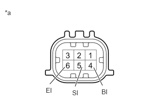
10.INSPECT REAR CORNER ULTRASONIC SENSOR LH
a.
E332147C33
2.188,1.833 2,1.448 true 1.604,1.854 1.75,1.438 true 1.063,1.802 1.385,1.438 true 0.104,0.188 0.417,0.344 0.313,0.156 10 false *a 0.979,1.854 1.292,2.01 0.313,0.156 10 false EI 1.542,1.906 1.854,2.063 0.313,0.156 10 false SI 2.167,1.885 2.479,2.042 0.313,0.156 10 false BI
*a Component without harness connected
(Rear Corner Ultrasonic Sensor LH)


Measure the resistance according to the value(s) in the table below.

Standard Resistance:
Tester Connection Condition Specified Condition
4 (BI) - 6 (EI) Always 10 kΩ or higher
4 (BI) - 1 Always Below 1 Ω
5 (SI) - 2 Always Below 30 Ω
6 (EI) - 3 Always Below 1 Ω


Result:
Proceed to
OK
NG


OK

11.REPLACE REAR CORNER ULTRASONIC SENSOR RH

NG

11.REPLACE REAR CORNER ULTRASONIC SENSOR RH

NEXT

12.CHECK DTC OUTPUT (C1AED)
a.

Clear the DTCs.

Body Electrical > IPA/ICS/Clearance Sonar > Clear DTCs
50002 170

b.

Check for DTCs.

Body Electrical > IPA/ICS/Clearance Sonar > Trouble Codes
50001 170

Result:
Result Proceed to
DTC C1AED is output A
No DTCs are output B


A

13.REPLACE REAR CENTER ULTRASONIC SENSOR RH

B

END (REAR CORNER ULTRASONIC SENSOR RH WAS DEFECTIVE)

13.REPLACE REAR CENTER ULTRASONIC SENSOR RH

NEXT

14.CHECK DTC OUTPUT (C1AED)
a.

Clear the DTCs.

Body Electrical > IPA/ICS/Clearance Sonar > Clear DTCs
50002 170

b.

Check for DTCs.

Body Electrical > IPA/ICS/Clearance Sonar > Trouble Codes
50001 170

Result:
Result Proceed to
DTC C1AED is output A
No DTCs are output B


A

15.REPLACE REAR CENTER ULTRASONIC SENSOR LH

B

END (REAR CENTER ULTRASONIC SENSOR RH WAS DEFECTIVE)

15.REPLACE REAR CENTER ULTRASONIC SENSOR LH

NEXT

16.CHECK DTC OUTPUT (C1AED)
a.

Clear the DTCs.

Body Electrical > IPA/ICS/Clearance Sonar > Clear DTCs
50002 170

b.

Check for DTCs.

Body Electrical > IPA/ICS/Clearance Sonar > Trouble Codes
50001 170

Result:
Result Proceed to
DTC C1AED is output A
No DTCs are output B


A

17.REPLACE REAR CORNER ULTRASONIC SENSOR LH

B

END (REAR CENTER ULTRASONIC SENSOR LH WAS DEFECTIVE)

17.REPLACE REAR CORNER ULTRASONIC SENSOR LH

NEXT

18.CHECK DTC OUTPUT (C1AED)
a.

Clear the DTCs.

Body Electrical > IPA/ICS/Clearance Sonar > Clear DTCs
50002 170

b.

Check for DTCs.

Body Electrical > IPA/ICS/Clearance Sonar > Trouble Codes
50001 170

Result:
Result Proceed to
DTC C1AED is output A
No DTCs are output B


A

B

END (REAR CORNER ULTRASONIC SENSOR LH WAS DEFECTIVE)