AUDIO / VIDEO AUDIO AND VISUAL SYSTEM B1579 Voice Recognition Microphone Disconnected
DESCRIPTION
The radio and display receiver assembly, roof console box sub-assembly and telephone microphone assembly are connected to each other using the microphone connection detection signal lines.
This DTC is stored when a microphone connection detection signal line is disconnected.
| DTC No. | Detection Item | DTC Detection Condition | Trouble Area |
|---|---|---|---|
| B1579 | Voice Recognition Microphone Disconnected | Microphone signal is lost | ·
Roof console box sub-assembly ·
Telephone microphone assembly ·
Radio and display receiver assembly ·
Harness or connector |
WIRING DIAGRAM
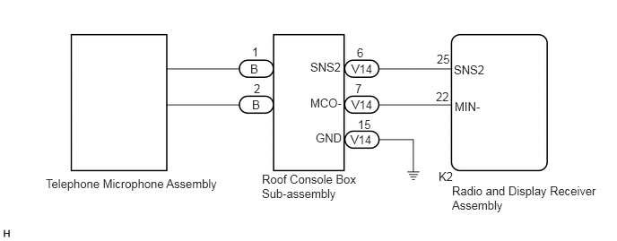
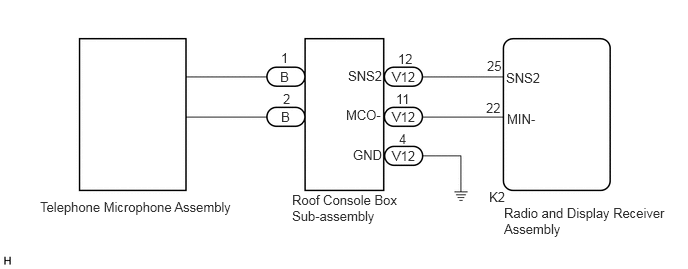
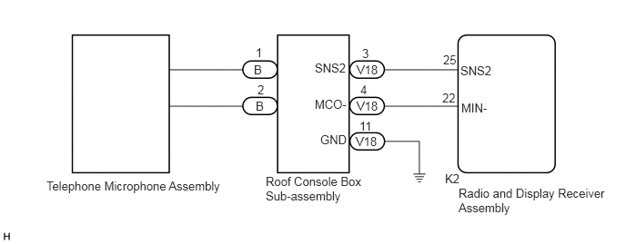
CAUTION / NOTICE / HINT
- NOTICE:
- ·
Depending on the parts that are replaced during vehicle inspection or maintenance, performing initialization, registration or calibration may be needed. Refer to Precaution for Audio and Visual System.
Click hereAudio / Visual / Telematics>AUDIO / VIDEO>AUDIO AND VISUAL SYSTEM>PRECAUTION
·When replacing the radio and display receiver assembly, always replace it with a new one. If a radio and display receiver assembly which was installed to another vehicle is used, the following may occur:
-A communication malfunction DTC may be stored.
-The radio and display receiver assembly may not operate normally.
PROCEDURE
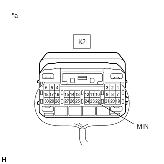
| *a | Component with harness connected
(Radio and Display Receiver Assembly) |
Measure the resistance according to the value(s) in the table below.
- Standard Resistance:
Tester Connection Condition Specified Condition K2-22 (MIN-) - Body ground Always Below 1 Ω
- Result:
Result Proceed to OK (w/ Sliding Roof) A OK (w/o Sliding Roof and w/o Telematics Transceiver) B OK (w/o Sliding Roof and w/ Telematics Transceiver) C NG D
A
B
C
D
Disconnect the K2 radio and display receiver assembly connector.
Disconnect the V14 roof console box sub-assembly connector.
Measure the resistance according to the value(s) in the table below.
- Standard Resistance:
Tester Connection Condition Specified Condition K2-25 (SNS2) - V14-6 (SNS2) Always Below 1 Ω K2-22 (MIN-) - V14-7 (MCO-) Always Below 1 Ω K2-25 (SNS2) or V14-6 (SNS2) - Body ground Always 10 kΩ or higher K2-22 (MIN-) or V14-7 (MCO-) - Body ground Always 10 kΩ or higher
- Result:
Proceed to OK NG
OK
NG
Remove the roof console box sub-assembly.
Click hereVehicle Interior>LIGHTING (INT)>PERSONAL LIGHT>REMOVAL
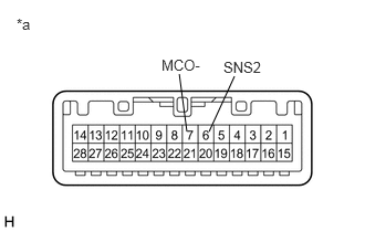
| *a | Component without harness connected
(Roof Console Box Sub-assembly) |
Measure the resistance according to the value(s) in the table below.
- Standard Resistance:
Tester Connection Condition Specified Condition 6 (SNS2) - 7 (MCO-) Always Below 1 Ω
- Result:
Proceed to OK NG
OK
NG
Remove the roof console box sub-assembly.
Click hereVehicle Interior>LIGHTING (INT)>PERSONAL LIGHT>REMOVAL
Disconnect the B telephone microphone assembly connector.
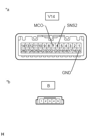
| *a | Component without harness connected
(Roof Console Box Sub-assembly (No. 1 Roof Wire Side)) |
| *b | Component without harness connected
(Roof Console Box Sub-assembly (Telephone Microphone Assembly Side)) |
Measure the resistance according to the value(s) in the table below.
- Standard Resistance:
Tester Connection Condition Specified Condition B-1 - V14-6 (SNS2) Always Below 1 Ω B-2 - V14-7 (MCO-) Always Below 1 Ω B-1 or V14-6 (SNS2) - V14-15 (GND) Always 10 kΩ or higher B-2 or V14-7 (MCO-) - V14-15 (GND) Always 10 kΩ or higher
- Result:
Proceed to OK NG
OK
NG
Disconnect the K2 radio and display receiver assembly connector.
Disconnect the V12 roof console box sub-assembly connector.
Measure the resistance according to the value(s) in the table below.
- Standard Resistance:
Tester Connection Condition Specified Condition K2-25 (SNS2) - V12-12 (SNS2) Always Below 1 Ω K2-22 (MIN-) - V12-11 (MCO-) Always Below 1 Ω K2-25 (SNS2) or V12-12 (SNS2) - Body ground Always 10 kΩ or higher K2-22 (MIN-) or V12-11 (MCO-) - Body ground Always 10 kΩ or higher
- Result:
Proceed to OK NG
OK
NG
Remove the roof console box sub-assembly.
Click hereVehicle Interior>LIGHTING (INT)>PERSONAL LIGHT>REMOVAL
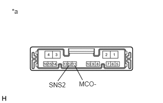
| *a | Component without harness connected
(Roof Console Box Sub-assembly) |
Measure the resistance according to the value(s) in the table below.
- Standard Resistance:
Tester Connection Condition Specified Condition 12 (SNS2) - 11 (MCO-) Always Below 1 Ω
- Result:
Proceed to OK NG
OK
NG
Remove the roof console box sub-assembly.
Click hereVehicle Interior>LIGHTING (INT)>PERSONAL LIGHT>REMOVAL
Disconnect the B telephone microphone assembly connector.
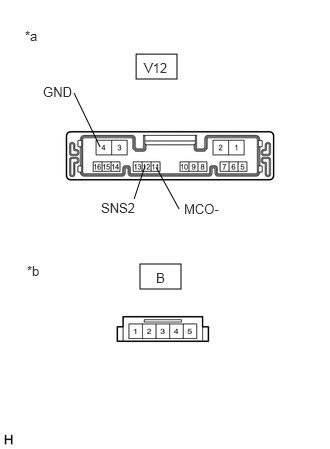
| *a | Component without harness connected
(Roof Console Box Sub-assembly (No. 1 Roof Wire Side)) |
| *b | Component without harness connected
(Roof Console Box Sub-assembly (Telephone Microphone Assembly Side)) |
Measure the resistance according to the value(s) in the table below.
- Standard Resistance:
Tester Connection Condition Specified Condition B-1 - V12-12 (SNS2) Always Below 1 Ω B-2 - V12-11 (MCO-) Always Below 1 Ω B-1 or V12-12 (SNS2) - V12-4 (GND) Always 10 kΩ or higher B-2 or V12-11 (MCO-) - V12-4 (GND) Always 10 kΩ or higher
- Result:
Proceed to OK NG
OK
NG
Disconnect the K2 radio and display receiver assembly connector.
Disconnect the V18 roof console box sub-assembly connector.
Measure the resistance according to the value(s) in the table below.
- Standard Resistance:
Tester Connection Condition Specified Condition K2-25 (SNS2) - V18-3 (SNS2) Always Below 1 Ω K2-22 (MIN-) - V18-4 (MCO-) Always Below 1 Ω K2-25 (SNS2) or V18-3 (SNS2) - Body ground Always 10 kΩ or higher K2-22 (MIN-) or V18-4 (MCO-) - Body ground Always 10 kΩ or higher
- Result:
Proceed to OK NG
OK
NG
Remove the roof console box sub-assembly.
Click hereVehicle Interior>LIGHTING (INT)>PERSONAL LIGHT>REMOVAL
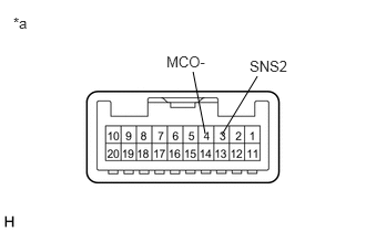
| *a | Component without harness connected
(Roof Console Box Sub-assembly) |
Measure the resistance according to the value(s) in the table below.
- Standard Resistance:
Tester Connection Condition Specified Condition 3 (SNS2) - 4 (MCO-) Always Below 1 Ω
- Result:
Proceed to OK NG
OK
NG
Remove the roof console box sub-assembly.
Click hereVehicle Interior>LIGHTING (INT)>PERSONAL LIGHT>REMOVAL
Disconnect the B telephone microphone assembly connector.
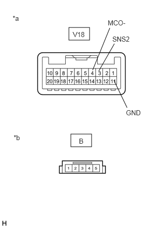
| *a | Component without harness connected
(Roof Console Box Sub-assembly (No. 1 Roof Wire Side)) |
| *b | Component without harness connected
(Roof Console Box Sub-assembly (Telephone Microphone Assembly Side)) |
Measure the resistance according to the value(s) in the table below.
- Standard Resistance:
Tester Connection Condition Specified Condition B-1 - V18-3 (SNS2) Always Below 1 Ω B-2 - V18-4 (MCO-) Always Below 1 Ω B-1 or V18-3 (SNS2) - V18-11 (GND) Always 10 kΩ or higher B-2 or V18-4 (MCO-) - V18-11 (GND) Always 10 kΩ or higher
- Result:
Proceed to OK NG
OK
NG