HYBRID / BATTERY CONTROL BATTERY VOLTAGE SENSOR(for NICKEL METAL HYDRIDE BATTERY) REMOVAL
CAUTION / NOTICE / HINT
The necessary procedures (adjustment, calibration, initialization, or registration) that must be performed after parts are removed and installed, or replaced during battery voltage sensor removal/installation are shown below.
| Replaced Part or Performed Procedure | Necessary Procedures | Effect/Inoperative Function when Necessary Procedures not Performed | Link |
|---|---|---|---|
| Auxiliary battery terminal is disconnected/reconnected | Perform steering sensor zero point calibration | Lane Tracing Assist System | ( ) |
| Pre-collision System | |||
| Memorize steering angle neutral point | Parking Assist Monitor System | ()
|
|
| Panoramic View Monitor System | ()
|
||
| Replacement of HV battery | Battery status info update | HV battery status information cannot be updated | ()
|
- CAUTION:
- ·
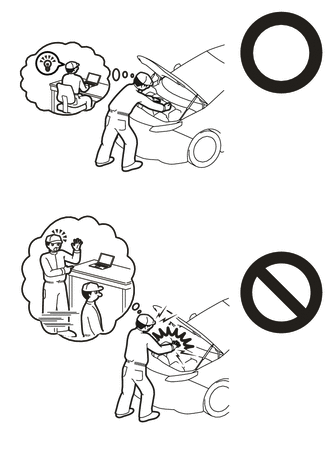
Orange wire harnesses and connectors indicate high-voltage circuits. To prevent electric shock, always follow the procedure described in the repair manual.
·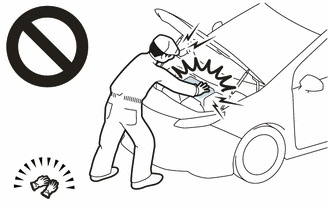
To prevent electric shock, wear insulated gloves when working on wire harnesses and components of the high voltage system.
- NOTICE:
- ·
After the power switch is turned off, the radio and display receiver assembly records various types ofmemory and settings. As a result, after turning the power switch off, make sure to wait at least 85seconds before disconnecting the cable from the negative (-) auxiliary battery terminal.
·The type of battery voltage sensor to be used varies depending on the vehicle model.
·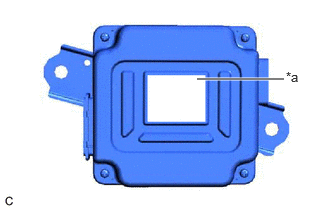 2.052,0.823 2.958,0.823 true 2.979,0.719 3.292,0.875 0.313,0.156 10 false *a
*a Blue Label
The type of battery voltage sensor can be confirmed by the color of the label.
·If the wrong type of battery voltage sensor is installed, the power switch cannot be turned on (READY).
·After installing the battery voltage sensor, perform the following to check that the power switch can be turned on (READY).
-Turn the power switch on (READY).
-Turn the power switch off and wait for 30 seconds or more.
-Turn the power switch on (READY) again.
PROCEDURE

 G9510
1.REMOVE HV BATTERY
G920NB
2.REMOVE UPPER HV BATTERY COVER SUB-ASSEMBLY
- CAUTION:
-
Be sure to wear insulated gloves and protective goggles.
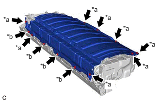
| *a | Bolt |
| *b | Nut |
Remove the 8 bolts, 4 nuts and upper HV battery cover sub-assembly from the HV battery.
G92Q1
3.REMOVE NO. 1 HV BATTERY SHIELD PANEL
- CAUTION:
-
Be sure to wear insulated gloves and protective goggles.
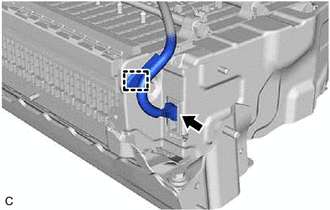
Disengage the clamp.
Disconnect the battery voltage sensor connector.
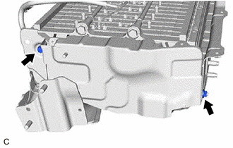
Remove the bolt and nut.
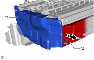
| *1 | No. 1 HV Battery Shield Panel |
| *2 | Rear No. 1 HV Battery Shield |

|
Pull Back |
Pull back the rear No. 1 HV battery shield and remove the No. 1 HV battery shield panel from the HV battery.
89892A
4.REMOVE BATTERY VOLTAGE SENSOR
- CAUTION:
-
Be sure to wear insulated gloves and protective goggles.
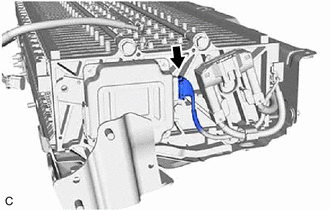
Disconnect the battery voltage sensor connector.
- NOTICE:
-
Insulate each disconnected high-voltage connector with insulating tape. Wrap the connector from the wire harness side to the end of the connector.
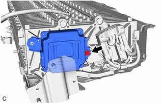
Remove the bolt and battery voltage sensor from the HV battery.
- NOTICE:
-
If the battery voltage sensor has been struck or dropped, replace it.