INTRODUCTION WHEN REMOVING,INSTALLING OR REPLACING PARTS WHEEL ALIGNMENT STANDARD
MEASURE VEHICLE HEIGHT (for 1BZ-FPE)
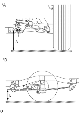
Bounce the vehicle up and down at the corners to stabilize the suspension and measure the vehicle height.
- Measuring points:
- Front Side A:
Ground clearance of lower arm front side cam bolt front center
- Rear Side B:
Ground clearance of rear leaf spring front side bolt center
| *A | for Front Side |
| *B | for Rear Side |
- Standard Vehicle Height (Unloaded Vehicle):
Vehicle Model Front Side A Rear Side B
(Reference)BZB70R-ZCMSC5 262 mm
(10.31 in.)326 mm
(12.83 in.)
- NOTICE:
-
Before inspecting the wheel alignment, check the vehicle height.
INSPECT CAMBER, CASTER AND STEERING AXIS INCLINATION (for 1BZ-FPE)
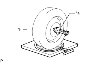
Install a camber-caster-kingpin gauge and place the front wheels on the center of a turning radius gauge.
| *a | Camber-caster-kingpin Gauge |
| *b | Turning Radius Gauge |
w/ Wheel Cap:
Remove the wheel cap.
Remove the front axle hub grease cap.
Remove the cotter pin and lock cap.
Align the end of the camber-caster-kingpin gauge center rod to the middle of the spindle and install the front axle hub to the camber-caster-kingpin gauge.
- NOTICE:
-
Take care not to apply grease to the camber-caster-kingpin gauge.
Inspect the camber, caster and steering axis inclination.
- Camber, caster and steering axis inclination (Unloaded Vehicle):
Camber Caster Steering Axis Inclination
(Reference)0°00' +/- 30'
(0.0° +/- 0.5°)4°30' +/- 30'
(4.5° +/- 0.5°)13°00'
(13.0°)
- NOTICE:
- ·
Perform the inspection while the vehicle is empty.
·The tolerance for the difference between the left and right wheels is 30' (0.5°) or less for both the camber and caster.
·Remove any garbage and foreign matter from the end of the axle hub before checking.
If the camber and caster are not as specified, adjust them.
If the steering axis inclination is not as specified after the camber and caster have been correctly adjusted, recheck the steering knuckle and front wheel for distortion and slack.
Remove the camber-caster-kingpin gauge.
Install the lock cap and a new cotter pin.
Install the front axle hub grease cap.
w/ Wheel Cap:
Install the wheel cap.
INSPECT TOE-IN (for 1BZ-FPE)
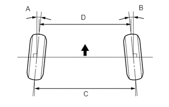
Bounce the vehicle up and down at the corners to stabilize the suspension and inspect toe-in.
- Toe-in (Unloaded Vehicle):
- A + B:
0°12' +/-5' (0.20° +/-0.08°)
- C - D:
2.5 +/- 1.0 mm (0.0984 +/- 0.0394 in.)
If the toe-in is not within the specified range, adjust it at the rack ends.
INSPECT WHEEL TURNING ANGLE (for 1BZ-FPE)
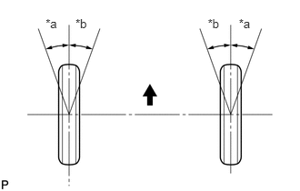
Turn the steering wheel fully, and measure the wheel turning angle.
- Wheel Turning Angle (Unloaded Vehicle):
Inside wheel Outside wheel
(Reference)39°30' +1°00'/-2°00'
(39.50°+1.00°/-2.00°)35°50'
(35.83°)
| *a | Inside |
| *b | Outside |

|
Front of the Vehicle |
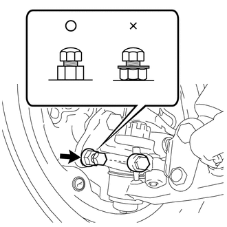
If the right and left wheel turning angles differ from the specified range, adjust the wheel turning angle with the knuckle stopper bolts.
Remove the knuckle stopper cover.
Secure the nut stopper bolt and loosen the lock nut.
Adjust the knuckle stopper bolt length.
Secure the nut stopper bolt and tighten the lock nut.
- Torque:
49 N*m (500 kgf*cm, 36 ft.*lbf)
- NOTICE:
-
Be sure to install the nut in the correct direction.
Install a new knuckle stopper cover.
MEASURE VEHICLE HEIGHT (for 1HZ)
Bounce the vehicle up and down at the corners to stabilize the suspension and measure the vehicle height.
- Measuring points:
- Front Side A:
Ground clearance of lower arm front side cam bolt front center
- Rear Side B:
Ground clearance of rear leaf spring front side bolt center
| *A | for Front Side |
| *B | for Rear Side |
- Standard Vehicle Height (Unloaded Vehicle):
Vehicle Model Tire Size Front Side A Spring Type Rear Side B
(Reference)HZB70L-ZGMRS 215/70R17.5 278 mm
(10.94 in.)2-Leaf Spring 337 mm
(13.27 in.)8-Leaf Spring 333 mm
(13.11 in.)7.00R16 296 mm
(11.65 in.)2-Leaf Spring 352 mm
(13.86 in.)8-Leaf Spring 348 mm
(13.70 in.)HZB70L-ZGMSS 215/70R17.5 278 mm
(10.94 in.)2-Leaf Spring 336 mm
(13.23 in.)8-Leaf Spring 332 mm
(13.07 in.)7.00R16 292 mm
(11.50 in.)2-Leaf Spring 350 mm
(13.78 in.)8-Leaf Spring 346 mm
(13.62 in.)HZB70L-ZGMSSV 215/70R17.5 273 mm
(10.75 in.)2-Leaf Spring 338 mm
(13.31 in.)8-Leaf Spring 334 mm
(13.15 in.)HZB70L-ZXMSS 215/70R17.5 278 mm
(10.94 in.)2-Leaf Spring 338 mm
(13.31 in.)8-Leaf Spring 334 mm
(13.15 in.)7.00R16 292 mm
(11.50 in.)2-Leaf Spring 352 mm
(13.86 in.)8-Leaf Spring 348 mm
(13.70 in.)HZB70L-ZXMSSV 215/70R17.5 273 mm
(10.75 in.)2-Leaf Spring 339 mm
(13.35 in.)8-Leaf Spring 335 mm
(13.19 in.)HZB70R-ZGMSS 215/70R17.5 278 mm
(10.94 in.)2-Leaf Spring 337 mm
(13.27 in.)8-Leaf Spring 333 mm
(13.11 in.)7.00R16 292 mm
(11.50 in.)2-Leaf Spring 351 mm
(13.82 in.)8-Leaf Spring 347 mm
(13.66 in.)HZB70R-ZGMNS 215/70R17.5 278 mm
(10.94 in.)2-Leaf Spring 335 mm
(13.19 in.)8-Leaf Spring 331 mm
(13.03 in.)7.00R16 292 mm
(11.50 in.)2-Leaf Spring 349 mm
(13.74 in.)8-Leaf Spring 346 mm
(13.62 in.)HZB70L-ZGMNS 215/70R17.5 273 mm
(10.75 in.)2-Leaf Spring 332 mm
(13.03 in.)8-Leaf Spring 328 mm
(12.91 in.)7.00R16 292 mm
(11.50 in.)2-Leaf Spring 347 mm
(13.66 in.)8-Leaf Spring 343 mm
(13.50 in.)HZB70L-ZGMTS 215/70R17.5 278 mm
(10.94 in.)2-Leaf Spring 334 mm
(13.15 in.)8-Leaf Spring 331 mm
(13.03 in.)7.00R16 292 mm
(11.50 in.)2-Leaf Spring 348 mm
(13.70 in.)8-Leaf Spring 345 mm
(13.58 in.)HZB70L-ZGMNSV 215/70R17.5 273 mm
(10.75 in.)2-Leaf Spring 334 mm
(13.15 in.)8-Leaf Spring 330 mm
(12.99 in.)
- NOTICE:
-
Before inspecting the wheel alignment, check the vehicle height.
INSPECT CAMBER, CASTER AND STEERING AXIS INCLINATION (for 1HZ)
Install a camber-caster-kingpin gauge and place the front wheels on the center of a turning radius gauge.
| *a | Camber-caster-kingpin Gauge |
| *b | Turning Radius Gauge |
w/ Wheel Cap:
Remove the wheel cap.
Remove the front axle hub grease cap.
Remove the cotter pin and lock cap.
Align the end of the camber-caster-kingpin gauge center rod to the middle of the spindle and install the front axle hub to the camber-caster-kingpin gauge.
- NOTICE:
-
Take care not to apply grease to the camber-caster-kingpin gauge.
Inspect the camber, caster and steering axis inclination.
- Camber, caster and steering axis inclination (Unloaded Vehicle):
Camber Caster Steering Axis Inclination
(Reference)0°00' +/- 30'
(0.0° +/- 0.5°)4°30' +/- 30'
(4.5° +/- 0.5°)13°00'
(13.0°)
- NOTICE:
- ·
Perform the inspection while the vehicle is empty.
·The tolerance for the difference between the left and right wheels is 30' (0.5°) or less for both the camber and caster.
·Remove any garbage and foreign matter from the end of the axle hub before checking.
If the camber and caster are not as specified, adjust them.
If the steering axis inclination is not as specified after the camber and caster have been correctly adjusted, recheck the steering knuckle and front wheel for distortion and slack.
Remove the camber-caster-kingpin gauge.
Install the lock cap and a new cotter pin.
Install the front axle hub grease cap.
w/ Wheel Cap:
Install the wheel cap.
INSPECT TOE-IN (for 1HZ)
Bounce the vehicle up and down at the corners to stabilize the suspension and inspect toe-in.
- Toe-in (Unloaded Vehicle):
Tire Size A + B C - D 215/70R17.5 0°12' +/-5'
(0.20° +/-0.08°)2.5 +/- 1.0 mm
(0.0984 +/- 0.0394 in.)7.00R16 0°16' +/-4'
(0.26° +/-0.07°)3.5 +/- 1.0 mm
(0.138 +/- 0.0394 in.)
|
|
Front of the Vehicle |
If the toe-in is not within the specified range, adjust it at the rack ends.
INSPECT WHEEL TURNING ANGLE (for 1HZ)
Turn the steering wheel fully, and measure the wheel turning angle.
- Wheel Turning Angle (Unloaded Vehicle):
Inside wheel Outside wheel
(Reference)39°30' +1°00'/-2°00'
(39.50°+1.00°/-2.00°)35°50'
(35.83°)
| *a | Inside |
| *b | Outside |
|
|
Front of the Vehicle |
If the right and left wheel turning angles differ from the specified range, adjust the wheel turning angle with the knuckle stopper bolts.
Remove the knuckle stopper cover.
Secure the nut stopper bolt and loosen the lock nut.
Adjust the knuckle stopper bolt length.
Secure the nut stopper bolt and tighten the lock nut.
- Torque:
49 N*m (500 kgf*cm, 36 ft.*lbf)
- NOTICE:
-
Be sure to install the nut in the correct direction.
Install a new knuckle stopper cover.
MEASURE VEHICLE HEIGHT (for 14B)
Bounce the vehicle up and down at the corners to stabilize the suspension and measure the vehicle height.
- Measuring points:
- Front Side A:
Ground clearance of lower arm front side cam bolt front center
- Rear Side B:
Ground clearance of rear leaf spring front side bolt center
| *A | for Front Side |
| *B | for Rear Side |
- Standard Vehicle Height (Unloaded Vehicle):
Vehicle Model Tire Size Front Side A Rear Side B
(Reference)BB60L-ZRMRS 215/70R17.5 278 mm
(10.94 in.)335 mm
(13.19 in.)7.00R16 292 mm
(11.50 in.)350 mm
(13.78 in.)BB60L-ZRMSS 215/70R17.5 273 mm
(10.75 in.)333 mm
(13.11 in.)7.00R16 292 mm
(11.50 in.)349 mm
(13.74 in.)BB60R-ZRMRS 215/70R17.5 278 mm
(10.94 in.)335 mm
(13.19 in.)7.00R16 292 mm
(11.50 in.)350 mm
(13.78 in.)BB60R-ZRMSS 215/70R17.5 273 mm
(10.75 in.)333 mm
(13.11 in.)7.00R16 292 mm
(11.50 in.)349 mm
(13.74 in.)
- NOTICE:
-
Before inspecting the wheel alignment, check the vehicle height.
INSPECT CAMBER, CASTER AND STEERING AXIS INCLINATION (for 14B)
Install a camber-caster-kingpin gauge and place the front wheels on the center of a turning radius gauge.
| *a | Camber-caster-kingpin Gauge |
| *b | Turning Radius Gauge |
w/ Wheel Cap:
Remove the wheel cap.
Remove the front axle hub grease cap.
Remove the cotter pin and lock cap.
Align the end of the camber-caster-kingpin gauge center rod to the middle of the spindle and install the front axle hub to the camber-caster-kingpin gauge.
- NOTICE:
-
Take care not to apply grease to the camber-caster-kingpin gauge.
Inspect the camber, caster and steering axis inclination.
- Camber, caster and steering axis inclination (Unloaded Vehicle):
Camber Caster Steering Axis Inclination
(Reference)0°00' +/- 30'
(0.0° +/- 0.5°)4°30' +/- 30'
(4.5° +/- 0.5°)13°00'
(13.0°)
- NOTICE:
- ·
Perform the inspection while the vehicle is empty.
·The tolerance for the difference between the left and right wheels is 30' (0.5°) or less for both the camber and caster.
·Remove any garbage and foreign matter from the end of the axle hub before checking.
If the camber and caster are not as specified, adjust them.
If the steering axis inclination is not as specified after the camber and caster have been correctly adjusted, recheck the steering knuckle and front wheel for distortion and slack.
Remove the camber-caster-kingpin gauge.
Install the lock cap and a new cotter pin.
Install the front axle hub grease cap.
w/ Wheel Cap:
Install the wheel cap.
INSPECT TOE-IN (for 14B)
Bounce the vehicle up and down at the corners to stabilize the suspension and inspect toe-in.
- Toe-in (Unloaded Vehicle):
Tire Size A + B C - D 215/70R17.5 0°12' +/-5'
(0.20° +/-0.08°)2.5 +/- 1.0 mm
(0.0984 +/- 0.0394 in.)7.00R16 0°16' +/-4'
(0.26° +/-0.07°)3.5 +/- 1.0 mm
(0.138 +/- 0.0394 in.)
|
|
Front of the Vehicle |
If the toe-in is not within the specified range, adjust it at the rack ends.
INSPECT WHEEL TURNING ANGLE (for 14B)
Turn the steering wheel fully, and measure the wheel turning angle.
- Wheel Turning Angle (Unloaded Vehicle):
Inside wheel Outside wheel
(Reference)39°30' +1°00'/-2°00'
(39.50°+1.00°/-2.00°)35°50'
(35.83°)
| *a | Inside |
| *b | Outside |
|
|
Front of the Vehicle |
If the right and left wheel turning angles differ from the specified range, adjust the wheel turning angle with the knuckle stopper bolts.
Remove the knuckle stopper cover.
Secure the nut stopper bolt and loosen the lock nut.
Adjust the knuckle stopper bolt length.
Secure the nut stopper bolt and tighten the lock nut.
- Torque:
49 N*m (500 kgf*cm, 36 ft.*lbf)
- NOTICE:
-
Be sure to install the nut in the correct direction.
Install a new knuckle stopper cover.
MEASURE VEHICLE HEIGHT (for 2TR-FE)
Bounce the vehicle up and down at the corners to stabilize the suspension and measure the vehicle height.
- Measuring points:
- Front Side A:
Ground clearance of lower arm front side cam bolt front center
- Rear Side B:
Ground clearance of rear leaf spring front side bolt center
| *A | for Front Side |
| *B | for Rear Side |
- Standard Vehicle Height (Unloaded Vehicle):
Vehicle Model Tire Size Front Side A Spring Type Rear Side B
(Reference)TRB60L-ZRMRK 215/70R17.5 278 mm
(10.94 in.)8-Leaf Spring 334 mm
(13.15 in.)7.00R16 292 mm
(11.50 in.)8-Leaf Spring 348 mm
(13.70 in.)TRB60L-ZRMSK 215/70R17.5 273 mm
(10.75 in.)8-Leaf Spring 333 mm
(13.11 in.)7.00R16 292 mm
(11.50 in.)8-Leaf Spring 348 mm
(13.70 in.)TRB60L-ZRMSKV 215/70R17.5 273 mm
(10.75 in.)8-Leaf Spring 335 mm
(13.19 in.)TRB70L-ZGMSK 215/70R17.5 278 mm
(10.94 in.)2-Leaf Spring 337 mm
(13.27 in.)8-Leaf Spring 334 mm
(13.15 in.)7.00R16 296 mm
(11.65 in.)2-Leaf Spring 352 mm
(13.86 in.)8-Leaf Spring 348 mm
(13.70 in.)TRB70L-ZGMSKV 215/70R17.5 278 mm
(10.94 in.)2-Leaf Spring 339 mm
(13.35 in.)8-Leaf Spring 335 mm
(13.19 in.)TRB70L-ZXMSKV 215/70R17.5 278 mm
(10.94 in.)2-Leaf Spring 340 mm
(13.39 in.)8-Leaf Spring 336.4 mm
(13.24 in.)TRB70L-ZGMNKV 215/70R17.5 278 mm
(10.94 in.)2-Leaf Spring 334 mm
(13.15 in.)8-Leaf Spring 331 mm
(13.03 in.)
- NOTICE:
-
Before inspecting the wheel alignment, check the vehicle height.
INSPECT CAMBER, CASTER AND STEERING AXIS INCLINATION (for 2TR-FE)
Install a camber-caster-kingpin gauge and place the front wheels on the center of a turning radius gauge.
| *a | Camber-caster-kingpin Gauge |
| *b | Turning Radius Gauge |
w/ Wheel Cap:
Remove the wheel cap.
Remove the front axle hub grease cap.
Remove the cotter pin and lock cap.
Align the end of the camber-caster-kingpin gauge center rod to the middle of the spindle and install the front axle hub to the camber-caster-kingpin gauge.
- NOTICE:
-
Take care not to apply grease to the camber-caster-kingpin gauge.
Inspect the camber, caster and steering axis inclination.
- Camber, caster and steering axis inclination (Unloaded Vehicle):
Camber Caster Steering Axis Inclination
(Reference)0°00' +/- 30'
(0.0° +/- 0.5°)4°30' +/- 30'
(4.5° +/- 0.5°)13°00'
(13.0°)
- NOTICE:
- ·
Perform the inspection while the vehicle is empty.
·The tolerance for the difference between the left and right wheels is 30' (0.5°) or less for both the camber and caster.
·Remove any garbage and foreign matter from the end of the axle hub before checking.
If the camber and caster are not as specified, adjust them.
If the steering axis inclination is not as specified after the camber and caster have been correctly adjusted, recheck the steering knuckle and front wheel for distortion and slack.
Remove the camber-caster-kingpin gauge.
Install the lock cap and a new cotter pin.
Install the front axle hub grease cap.
w/ Wheel Cap:
Install the wheel cap.
INSPECT TOE-IN (for 2TR-FE)
Bounce the vehicle up and down at the corners to stabilize the suspension and inspect toe-in.
- Toe-in (Unloaded Vehicle):
Tire Size A + B C - D 215/70R17.5 0°12' +/-5'
(0.20° +/-0.08°)2.5 +/- 1.0 mm
(0.0984 +/- 0.0394 in.)7.00R16 0°16' +/-4'
(0.26° +/-0.07°)3.5 +/- 1.0 mm
(0.138 +/- 0.0394 in.)
|
|
Front of the Vehicle |
If the toe-in is not within the specified range, adjust it at the rack ends.
INSPECT WHEEL TURNING ANGLE (for 2TR-FE)
Turn the steering wheel fully, and measure the wheel turning angle.
- Wheel Turning Angle (Unloaded Vehicle):
Inside wheel Outside wheel
(Reference)39°30' +1°00'/-2°00'
(39.50°+1.00°/-2.00°)35°50'
(35.83°)
| *a | Inside |
| *b | Outside |
|
|
Front of the Vehicle |
If the right and left wheel turning angles differ from the specified range, adjust the wheel turning angle with the knuckle stopper bolts.
Remove the knuckle stopper cover.
Secure the nut stopper bolt and loosen the lock nut.
Adjust the knuckle stopper bolt length.
Secure the nut stopper bolt and tighten the lock nut.
- Torque:
49 N*m (500 kgf*cm, 36 ft.*lbf)
- NOTICE:
-
Be sure to install the nut in the correct direction.
Install a new knuckle stopper cover.
MEASURE VEHICLE HEIGHT (for N04C-UH, N04C-VL, N04C-VQ)
Bounce the vehicle up and down at the corners to stabilize the suspension and measure the vehicle height.
- Measuring points:
- Front Side A:
Ground clearance of lower arm front side cam bolt front center
- Rear Side B:
Ground clearance of rear leaf spring front side bolt center
| *A | for Front Side |
| *B | for Rear Side |
- Standard Vehicle Height (Unloaded Vehicle):
Vehicle Model Tire Size Front Side A Spring Type Rear Side B
(Reference)XZB70L-ZEMSYR 215/70R17.5 262 mm
(10.31 in.)2-Leaf Spring 322 mm
(12.68 in.)XZB70L-ZGMRY 215/70R17.5 278 mm
(10.94 in.)2-Leaf Spring 338 mm
(13.31 in.)8-Leaf Spring 334 mm
(13.15 in.)7.00R16 292 mm
(11.50 in.)2-Leaf Spring 352 mm
(13.86 in.)8-Leaf Spring 348 mm
(13.70 in.)XZB70L-ZGMSY 215/70R17.5 273 mm
(10.75 in.)2-Leaf Spring 336 mm
(13.23 in.)8-Leaf Spring 332 mm
(13.07 in.)7.00R16 292 mm
(11.50 in.)2-Leaf Spring 351 mm
(13.82 in.)8-Leaf Spring 347 mm
(13.66 in.)XZB70L-ZXMSY 215/70R17.5 273 mm
(10.75 in.)2-Leaf Spring 336 mm
(13.23 in.)8-Leaf Spring 333 mm
(13.11 in.)7.00R16 292 mm
(11.50 in.)2-Leaf Spring 351 mm
(13.82 in.)8-Leaf Spring 348 mm
(13.70 in.)XZB70R-ZEMQY 215/70R17.5 262 mm
(10.31 in.)2-Leaf Spring 329 mm
(12.95 in.)XZB70R-ZEMSYQ 215/70R17.5 273 mm
(10.75 in.)2-Leaf Spring 334 mm
(13.15 in.)XZB70R-ZEPNYQ 215/70R17.5 273 mm
(10.75 in.)2-Leaf Spring 334 mm
(13.15 in.)XZB70R-ZEPQY 215/70R17.5 262 mm
(10.31 in.)2-Leaf Spring 329 mm
(12.95 in.)XZB70R-ZEPSYQ 215/70R17.5 273 mm
(10.75 in.)2-Leaf Spring 334 mm
(13.15 in.)XZB70R-ZEMSY 215/70R17.5 262 mm
(10.31 in.)2-Leaf Spring 327 mm
(12.87 in.)XZB70R-ZEPSY 215/70R17.5 262 mm
(10.31 in.)2-Leaf Spring 327 mm
(12.87 in.)XZB70L-ZGMNY 215/70R17.5 270 mm
(10.63 in.)2-Leaf Spring 329 mm
(12.95 in.)8-Leaf Spring 326 mm
(12.83 in.)7.00R16 286 mm
(11.26 in.)2-Leaf Spring 344 mm
(13.54 in.)8-Leaf Spring 340 mm
(13.39 in.)XZB70L-ZGMTY 215/70R17.5 273 mm
(10.75 in.)2-Leaf Spring 331 mm
(13.03 in.)8-Leaf Spring 327 mm
(12.87 in.)7.00R16 286 mm
(11.26 in.)2-Leaf Spring 345 mm
(13.58 in.)8-Leaf Spring 341 mm
(13.43 in.)XZB70R-ZEMNY 215/70R17.5 273 mm
(10.75 in.)2-Leaf Spring 335 mm
(13.19 in.)XZB70R-ZGMSY 215/70R17.5 273 mm
(10.75 in.)8-Leaf Spring 333 mm
(13.11 in.)XZB60L-ZRMSYV 215/70R17.5 262 mm
(10.31 in.)8-Leaf Spring 333 mm
(13.11 in.)XZB70L-ZGMSYV 215/70R17.5 270 mm
(10.63 in.)2-Leaf Spring 336 mm
(13.23 in.)8-Leaf Spring 333 mm
(13.11 in.)XZB70L-ZGMNYV 215/70R17.5 270 mm
(10.63 in.)2-Leaf Spring 332 mm
(13.07 in.)8-Leaf Spring 328 mm
(12.91 in.)XZB70L-ZXMSYV 215/70R17.5 270 mm
(10.63 in.)2-Leaf Spring 338 mm
(13.31 in.)8-Leaf Spring 334 mm
(13.15 in.)
- NOTICE:
-
Before inspecting the wheel alignment, check the vehicle height.
INSPECT CAMBER, CASTER AND STEERING AXIS INCLINATION (for N04C-UH, N04C-VL, N04C-VQ)
Install a camber-caster-kingpin gauge and place the front wheels on the center of a turning radius gauge.
| *a | Camber-caster-kingpin Gauge |
| *b | Turning Radius Gauge |
w/ Wheel Cap:
Remove the wheel cap.
Remove the front axle hub grease cap.
Remove the cotter pin and lock cap.
Align the end of the camber-caster-kingpin gauge center rod to the middle of the spindle and install the front axle hub to the camber-caster-kingpin gauge.
- NOTICE:
-
Take care not to apply grease to the camber-caster-kingpin gauge.
Inspect the camber, caster and steering axis inclination.
- Camber, caster and steering axis inclination (Unloaded Vehicle):
Camber Caster Steering Axis Inclination
(Reference)0°00' +/- 30'
(0.0° +/- 0.5°)4°30' +/- 30'
(4.5° +/- 0.5°)13°00'
(13.0°)
- NOTICE:
- ·
Perform the inspection while the vehicle is empty.
·The tolerance for the difference between the left and right wheels is 30' (0.5°) or less for both the camber and caster.
·Remove any garbage and foreign matter from the end of the axle hub before checking.
If the camber and caster are not as specified, adjust them.
If the steering axis inclination is not as specified after the camber and caster have been correctly adjusted, recheck the steering knuckle and front wheel for distortion and slack.
Remove the camber-caster-kingpin gauge.
Install the lock cap and a new cotter pin.
Install the front axle hub grease cap.
w/ Wheel Cap:
Install the wheel cap.
INSPECT TOE-IN (for N04C-UH, N04C-VL, N04C-VQ)
Bounce the vehicle up and down at the corners to stabilize the suspension and inspect toe-in.
- Toe-in (Unloaded Vehicle):
Tire Size A + B C - D 215/70R17.5 0°12' +/-5'
(0.20° +/-0.08°)2.5 +/- 1.0 mm
(0.0984 +/- 0.0394 in.)7.00R16 0°16' +/-4'
(0.26° +/-0.07°)3.5 +/- 1.0 mm
(0.138 +/- 0.0394 in.)
|
|
Front of the Vehicle |
If the toe-in is not within the specified range, adjust it at the rack ends.
INSPECT WHEEL TURNING ANGLE (for N04C-UH, N04C-VL, N04C-VQ)
Turn the steering wheel fully, and measure the wheel turning angle.
- Wheel Turning Angle (Unloaded Vehicle):
Inside wheel Outside wheel
(Reference)39°30' +1°00'/-2°00'
(39.50°+1.00°/-2.00°)35°50'
(35.83°)
| *a | Inside |
| *b | Outside |
|
|
Front of the Vehicle |
If the right and left wheel turning angles differ from the specified range, adjust the wheel turning angle with the knuckle stopper bolts.
Remove the knuckle stopper cover.
Secure the nut stopper bolt and loosen the lock nut.
Adjust the knuckle stopper bolt length.
Secure the nut stopper bolt and tighten the lock nut.
- Torque:
49 N*m (500 kgf*cm, 36 ft.*lbf)
- NOTICE:
-
Be sure to install the nut in the correct direction.
Install a new knuckle stopper cover.