BODY PANEL FIT STANDARD / ADJUSTMENT METHOD ADJUSTMENT
INSPECT FRONT DOOR PANEL SUB-ASSEMBLY RH
Check that the clearance measurements of areas A to E are within the standard ranges.
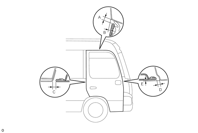
| Area | Measurement Condition | Specified Condition |
|---|---|---|
| A | 2 Coat Application | 4.3 to 7.3 mm (0.169 to 0.287 in.) |
| 4 Coat Application | 4.2 to 7.2 mm (0.165 to 0.283 in.) | |
| 2 Coat Application + Black Out Tape | 4.0 to 7.0 mm (0.157 to 0.276 in.) | |
| 4 Coat Application + Black Out Tape | 3.9 to 6.9 mm (0.154 to 0.272 in.) | |
| B | 2 Coat Application | 3.2 to 6.2mm (0.126 to 0.244 in.) |
| 4 Coat Application | 3.1 to 6.1mm (0.122 to 0.240 in.) | |
| 2 Coat Application + Black Out Tape | 2.9 to 5.9mm (0.114 to 0.232 in.) | |
| 4 Coat Application + Black Out Tape | 2.8 to 5.8mm (0.110 to 0.228 in.) | |
| C | 2 Coat Application | 4.4 to 7.4 mm (0.173 to 0.291 in.) |
| 4 Coat Application | 4.3 to 7.3 mm (0.169 to 0.287 in.) | |
| 2 Coat Application + Black Out Tape | 4.1 to 7.1 mm (0.161 to 0.280 in.) | |
| 4 Coat Application + Black Out Tape | 4.0 to 7.0 mm (0.157 to 0.276 in.) | |
| D | 2 Coat Application | 3.7 to 8.7 mm (0.146 to 0.343 in.) |
| 4 Coat Application | 3.6 to 8.6 mm (0.142 to 0.339 in.) | |
| 2 Coat Application + Black Out Tape | 3.4 to 8.4 mm (0.134 to 0.331 in.) | |
| 4 Coat Application + Black Out Tape | 3.3 to 8.3 mm (0.130 to 0.327 in.) | |
| E | 2 Coat Application | -0.9 to 4.1 mm (0.035 to 0.161 in.) |
| 4 Coat Application | -1.0 to 4.0 mm (0.039 to 0.157 in.) | |
| 2 Coat Application + Black Out Tape | -1.2 to 3.8 mm (0.047 to 0.149 in.) | |
| 4 Coat Application + Black Out Tape | -1.3 to 3.7 mm (0.051 to 0.146 in.) |
- HINT:
-
Centering bolts are used to mount the door hinge to the vehicle body and door. The door cannot be adjusted with the centering bolts on. Substitute the centering bolts for standard bolts when making adjustments.
ADJUST FRONT DOOR PANEL SUB-ASSEMBLY RH
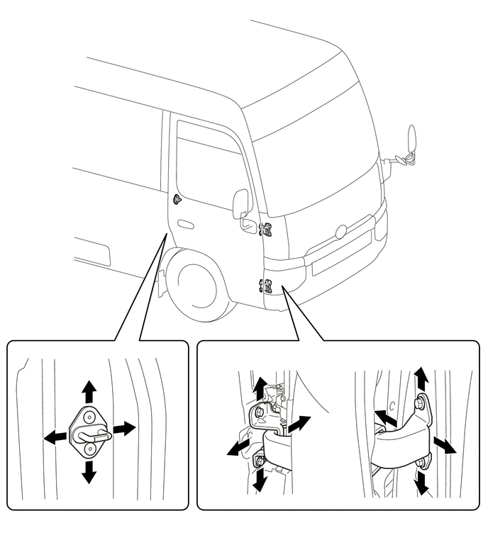
Using SST, loosen the body side bolt and adjust the horizontal and vertical axis of the door.
Tighten the body side bolt on the body after the adjustment.
- Torque:
- 24 N*m (245 kgf*cm, 18 ft.*lbf)
Loosen the door side bolt and adjust the vertical axis of the door and the horizontal axis for thefront of the door.
Tighten the door side bolts on the body after the adjustment.
- Torque:
- 32.5 N*m (331 kgf*cm, 24 ft.*lbf)
- NOTICE:
-
A center ring bolt is used in the factory assembly stage. Therefore, it is necessary toreplace it with a replacement bolt when performing adjustments.
Using a T40 "TORX" socket wrench, adjust the striker position by slightly loosening the strikermounting screws and hitting the striker with a brass bar and hammer.
Tighten the striker mounting screws on the body after the adjustment.
- Torque:
- 12 N*m (122 kgf*cm, 9 ft.*lbf)
INSPECT CENTER DOOR PANEL (for Glide Type)
Check that the clearance measurements of areas A to C are within the standard range.
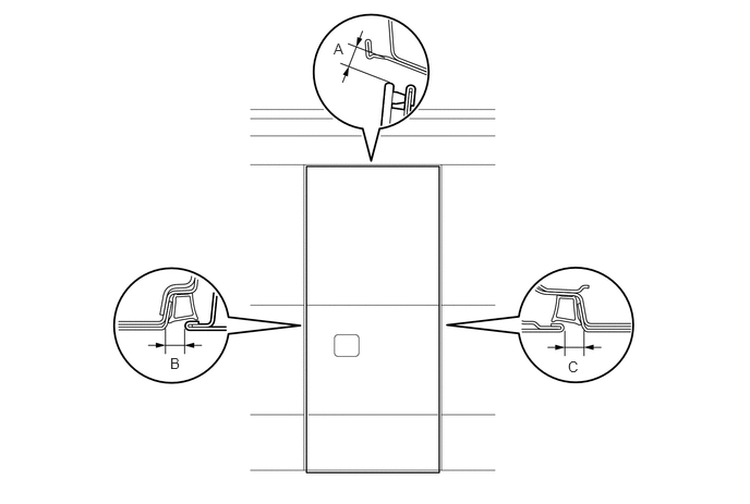
- Standard:
Area Measurement Condition Specified Condition A 2 Coat Application 6.6 to 12.6 mm (0.260 to 0.496 in.) 4 Coat Application 6.5 to 12.5 mm (0.256 to 0.492 in.) B 2 Coat Application 13.4 to 17.4mm (0.528 to 0.685 in.) 4 Coat Application 13.4 to 17.4mm (0.528 to 0.685 in.) C 2 Coat Application 13.4 to 17.4mm (0.528 to 0.685 in.) 4 Coat Application 13.3 to 17.3mm (0.524 to 0.681 in.)
ADJUST CENTER DOOR PANEL (for Glide Type)
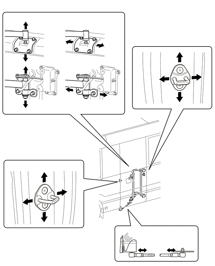
Loosen the glide door arm bracket link bolt and adjust the horizontal axis of the bottom of the door.
Tighten the glide door arm bracket link bolt after the adjustment.
- Torque:
- Upper side:
12 N*m (122 kgf*cm, 9 ft.*lbf)
- Lower side:
18 N*m (184 kgf*cm, 13 ft.*lbf)
Loosen the glide door link nut and adjust the horizontal axis of the bottom of the door.
Tighten the glide door link nut after the adjustment.
- Torque:
24.5 N*m (250 kgf*cm, 18 ft.*lbf)
Using a T40 "TORX" socket wrench, adjust the striker position by slightly loosening the striker mounting screws and hitting the striker with a brass bar and hammer.
Tighten the striker mounting screws on the body after the adjustment.
- Torque:
12 N*m (122 kgf*cm, 9 ft.*lbf)
INSPECT CENTER DOOR PANEL SUB-ASSEMBLY (for Folding Type)
Check that the clearance measurements of areas A to E are within the standard range.
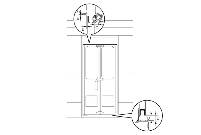
- Standard:
Area Measurement Condition Specified Condition A 2 Coat Application 5.5 to 8.5 mm (0.216 to 0.335 in.) 4 Coat Application 5.4 to 8.4 mm (0.213 to 0.331 in.) B 2 Coat Application 1.3 to 4.3mm (0.051 to 0.169 in.) 4 Coat Application 1.2 to 4.2mm (0.047 to 0.165 in.) C 2 Coat Application 12.1 to 15.1 mm (0.476 to 0.594 in.) 4 Coat Application 12.1 to 15.1 mm (0.476 to 0.594 in.) D 2 Coat Application 21.6 to 24.6 mm (0.850 to 0.970 in.) 4 Coat Application 21.6 to 24.6 mm (0.850 to 0.970 in.) E 2 Coat Application 24.4 to 27.4 mm (0.960 to 0.079 in.) 4 Coat Application 24.3 to 27.3 mm (0.957 to 0.075 in.)
INSPECT AUTO CENTER DOOR (for Glide Type)
Check that the clearance measurements of areas A to I are within the standard range.
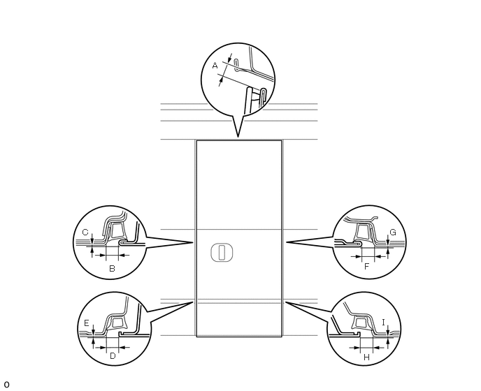
- Standard:
Area Specified Condition Area Specified Condition A 6.55 to 12.55 mm (0.258 to 0.494 in.) B 13.2 to 17.2 mm (0.520 to 0.677 in.) C -2.0 to 2.0 mm (-0.0787 to 0.0787 in.) D 13.2 to 17.2 mm (0.520 to 0.677 in.) E -2.0 to 2.0 mm (-0.0787 to 0.0787 in.) F 13.2 to 17.2 mm (0.520 to 0.677 in.) G -2.0 to 2.0 mm (-0.0787 to 0.0787 in.) H 13.2 to 17.2 mm (0.520 to 0.677 in.) I -2.0 to 2.0 mm (-0.0787 to 0.0787 in.) - -
ADJUST AUTO CENTER DOOR (for Glide Type)
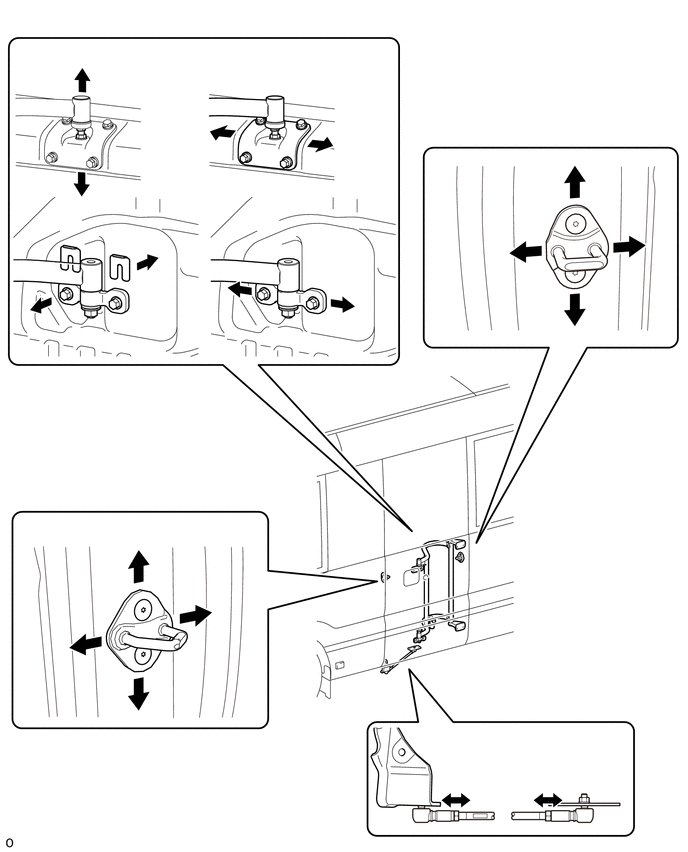
Loosen the glide door arm bracket link bolt and adjust the horizontal axis of the bottom of the door.
Tighten the glide door arm bracket link bolt and nut after the adjustment.
- Torque:
- Nut : 25 N*m (255 kgf*cm, 18 ft.*lbf)
- Bolt : 18 N*m (184 kgf*cm, 13 ft.*lbf)
Loosen the glide door link nut and adjust the horizontal axis of the bottom of the door.
Tighten the glide door link nut after the adjustment.
- Torque:
- 24.5 N*m (250 kgf*cm, 18 ft.*lbf)
Using a T40 "TORX" socket wrench, adjust the striker position by slightly loosening the striker mounting screws and hitting the striker with a brass bar and hammer.
Tighten the striker mounting screws on the body after the adjustment.
- Torque:
12 N*m (122 kgf*cm, 9 ft.*lbf)
INSPECT BACK DOOR PANEL SUB-ASSEMBLY
Check that the clearance measurements of areas A to H are within the standard range.
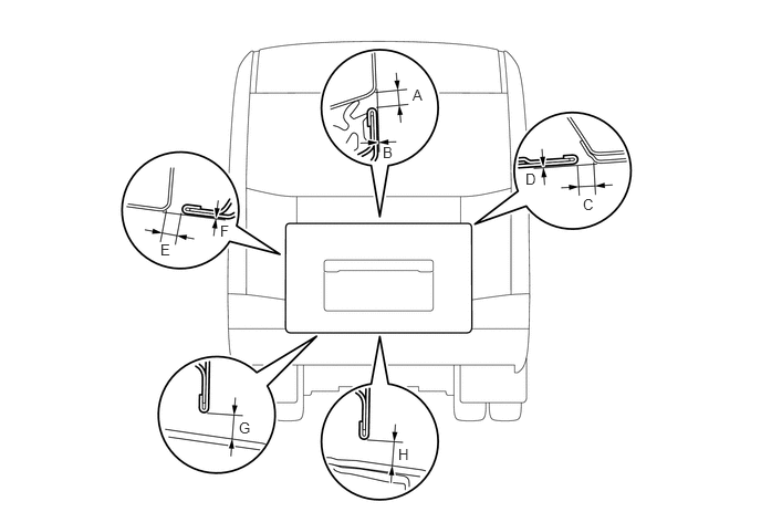
- Standard:
Area Specified Condition Area Specified Condition A 4.5 to 7.5 mm (0.177 to 0.296 in.) B -1.5 to 1.5 mm (-0.059 to 0.059 in.) C 4.5 to 7.5 mm (0.177 to 0.296 in.) D -1.5 to 1.5 mm (-0.059 to 0.059 in.) E 4.5 to 7.5 mm (0.177 to 0.296 in.) F -1.5 to 1.5 mm (-0.059 to 0.059 in.) G 7.2 to 12.2 mm (0.283 to 0.480 in.) H 7.5 to 12.5 mm (0.295 to 0.492 in.)
ADJUST BACK DOOR PANEL SUB-ASSEMBLY
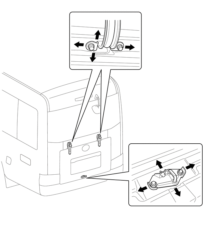
Loosen the body side bolt and adjust the front and rear and horizontal axis of the door.
Tighten the body side bolt on the body after the adjustment.
- Torque:
28 N*m (286 kgf*cm, 21 ft.*lbf)
Loosen the door side bolt and adjust the vertical axis of the door and the horizontal axis for the top of the door.
Tighten the door side bolt on the body after the adjustment.
Loosen the back door lock striker bolt and adjust the back door lock striker and the horizontal axis for the bottom of the door.
Tighten the back door lock striker bolt on the body after the adjustment.
- Torque:
7.5 N*m (76 kgf*cm, 66 in.*lbf)
INSPECT BACK DOOR PANEL SUB-ASSEMBLY RH (for Double Swing Out Type)
Check that the clearance measurements of areas A to F are within the standard range.
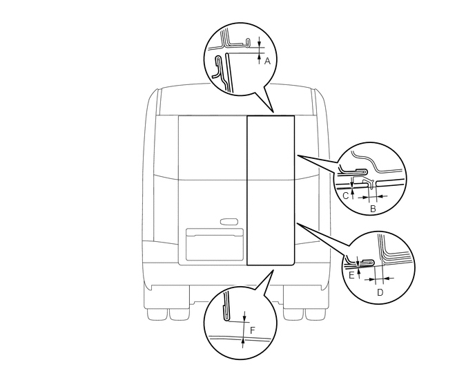
- Standard:
Area Specified Condition Area Specified Condition A 3.9 to 8.9 mm (0.154 to 0.350 in.) B 2.5 to 9.5 mm (0.098 to 0.374 in.) C -3.4 to 3.6 mm (-0.134 to 0.142 in.) D 4.5 to 7.5 mm (0.177 to 0.295 in.) E -1.4 to 1.6 mm (0.055 to 0.063 in.) F 7.5 to 13.5 mm (0.295 to 0.531 in.)
ADJUST BACK DOOR PANEL SUB-ASSEMBLY RH (for Double Swing Out Type)
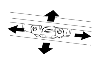
Loosen the back door upper lock striker and adjust the door's position.
Tighten the striker bolts on the door after the adjustment.
- Torque:
24 N*m (245 kgf*cm, 18 ft.*lbf)
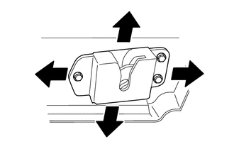
Loosen the lower back door lock assembly and adjust the door's position.
Tighten the back door lock bolts on the door afterthe adjustment.
- Torque:
7.5 N*m (76 kgf*cm, 66 in.*lbf)
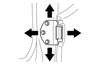
Loosen the back door hinge sub-assembly and adjust the door's position.
Tighten the hinge bolts on the door after the adjustment.
- Torque:
24 N*m (245 kgf*cm, 18 ft.*lbf)
INSPECT BACK DOOR PANEL SUB-ASSEMBLY LH (for Double Swing Out Type)
Check that the clearance measurements of areas A to H are within the standard range.
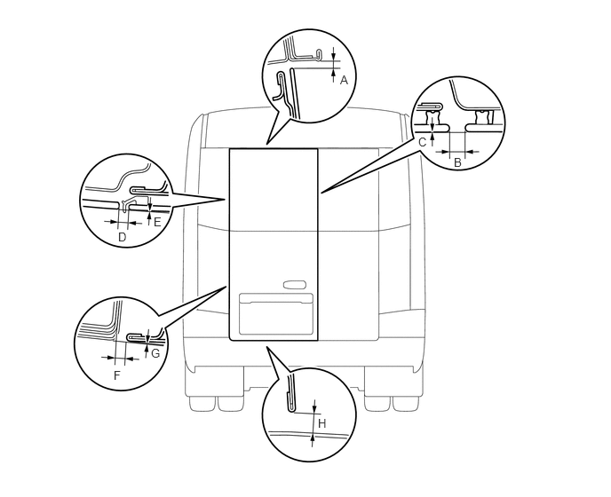
- Standard:
Area Specified Condition Area Specified Condition A 3.9 to 8.9 mm (0.154 to 0.350 in.) B 3.0 to 11.0 mm (0.118 to 0.433 in.) C -4.0 to 4.0 mm (-0.157 to 0.157 in.) D 2.5 to 9.5 mm (0.098 to 0.374 in.) E -3.5 to 3.5 mm (-0.138 to 0.138 in.) F 4.5 to 7.5 mm (0.177 to 0.295 in.) G -1.4 to 1.6 mm (0.055 to 0.063 in.) H 7.5 to 13.5 mm (0.295 to 0.531 in.)
ADJUST BACK DOOR PANEL SUB-ASSEMBLY LH (for Double Swing Out Type)
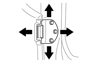
Loosen the back door hinge sub-assembly and adjust the door's position.
Tighten the hinge bolts on the door after the adjustment.
- Torque:
24 N*m (245 kgf*cm, 18 ft.*lbf)
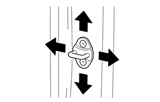
Using a T40 "TORX" socket wrench, adjust the striker position by slightly loosening the striker mounting screws and hitting the striker with a brass bar and hammer.
Using a T40 "TORX" socket wrench, tighten the striker mounting screws after the adjustment.
- Torque:
12 N*m (122 kgf*cm, 9 ft.*lbf)
INSPECT BACK DOOR PANEL SUB-ASSEMBLY RH (for Emergency Door)
Check that the clearance measurements of areas A to F are within the standard range.
- Standard:
Area Specified Condition Area Specified Condition A 3.9 to 8.9 mm (0.154 to 0.350 in.) B 2.5 to 9.5 mm (0.098 to 0.374 in.) C -3.4 to 3.6 mm (-0.134 to 0.142 in.) D 4.5 to 7.5 mm (0.177 to 0.295 in.) E -1.4 to 1.6 mm (0.055 to 0.063 in.) F 7.5 to 13.5 mm (0.295 to 0.531 in.)
ADJUST BACK DOOR PANEL SUB-ASSEMBLY RH (for Emergency Door)
Loosen the back door upper lock striker and adjust the door's position.
Tighten the striker bolts on the door after the adjustment.
- Torque:
24 N*m (245 kgf*cm, 18 ft.*lbf)
Loosen the lower back door lock assembly and adjust the door's position.
Tighten the back door lock bolts on the door after the adjustment.
- Torque:
7.5 N*m (76 kgf*cm, 66 in.*lbf)
Loosen the back door hinge sub-assembly and adjust the door's position.
Tighten the hinge bolts on the door after the adjustment.
- Torque:
24 N*m (245 kgf*cm, 18 ft.*lbf)
INSPECT BACK DOOR PANEL SUB-ASSEMBLY LH (for Emergency Door)
Check that the clearance measurements of areas A to H are within the standard range.
- Standard:
Area Specified Condition Area Specified Condition A 3.9 to 8.9 mm (0.154 to 0.350 in.) B 3.0 to 11.0 mm (0.118 to 0.433 in.) C -4.0 to 4.0 mm (-0.157 to 0.157 in.) D 2.5 to 9.5 mm (0.098 to 0.374 in.) E -3.5 to 3.5 mm (-0.138 to 0.138 in.) F 4.5 to 7.5 mm (0.177 to 0.295 in.) G -1.4 to 1.6 mm (0.055 to 0.063 in.) H 7.5 to 13.5 mm (0.295 to 0.531 in.)
ADJUST BACK DOOR PANEL SUB-ASSEMBLY LH (for Emergency Door)
Loosen the back door hinge sub-assembly and adjust the door's position.
Tighten the hinge bolts on the door after the adjustment.
- Torque:
24 N*m (245 kgf*cm, 18 ft.*lbf)
Using a T40 "TORX" socket wrench, adjust the striker position by slightly loosening the striker mounting screws and hitting the striker with a brass bar and hammer.
Using a T40 "TORX" socket wrench, tighten the striker mounting screws after the adjustment.
- Torque:
12 N*m (122 kgf*cm, 9 ft.*lbf)