NM2850E
_58
Vehicle Interior
_074251
HEATING / AIR CONDITIONING
_0361397
AIR CONDITIONING SYSTEM
DE
DETAILS
F
HEATING / AIR CONDITIONING AIR CONDITIONING SYSTEM DETAILS AIR CONDITIONING UNIT
CONSTRUCTION
a.
Room Cooler Unit
i.
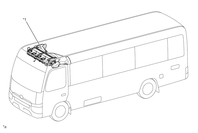
A room cooler unit (cooler unit assembly) for the manual air conditioner has been adopted in the roof section at the front of the vehicle and provided depending on the specifications.
Room Cooler Unit (Cooler Unit Assembly) Parts Location
1.479,1.719 0.948,0.781
true
0.823,0.625 1.135,0.823
0.313,0.198
10
false
*1
0.104,4.51 0.417,4.708
0.313,0.198
10
false
*a
| *1 | Room Cooler Unit (Cooler Unit Assembly) | - | - |
| *a | The illustrations shown are examples only. | - | - |
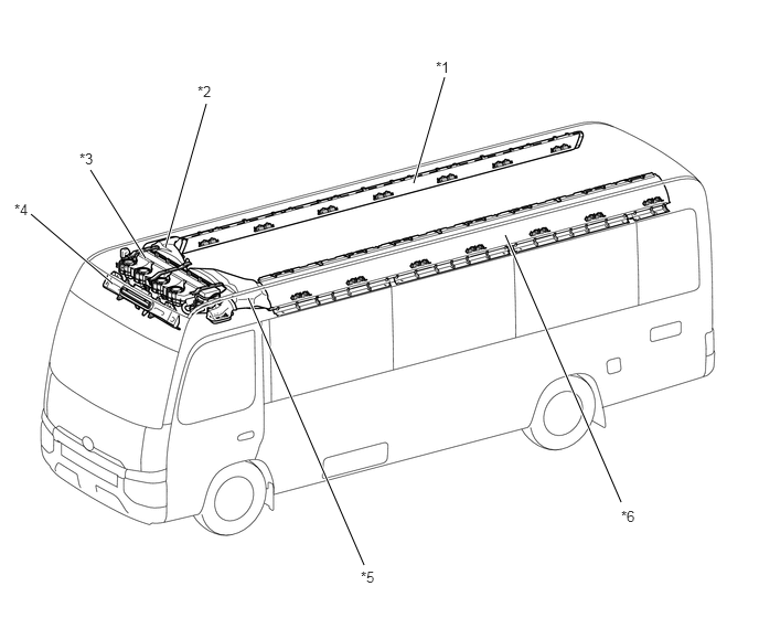
Room Cooler Air Duct Parts Location
5.865,4.74 4.771,2.219
true
3.438,5.333 2.344,2.813
true
1.948,0.979 1.563,2.333
true
0.854,1.604 1.375,2.438
true
0.292,2.021 1.063,2.677
true
4.198,0.729 3.906,1.729
true
4.115,0.552 4.427,0.75
0.313,0.198
10
false
*1
1.865,0.781 2.177,0.979
0.313,0.198
10
false
*2
0.75,1.417 1.063,1.615
0.313,0.198
10
false
*3
0.135,1.896 0.448,2.094
0.313,0.198
10
false
*4
3.406,5.365 3.719,5.563
0.313,0.198
10
false
*5
5.865,4.792 6.177,4.99
0.313,0.198
10
false
*6
| *1 | Inner Cooler Duct RH | *2 | No. 1 Air Duct Assembly |
| *3 | Room Cooler Unit (Cooler Unit Assembly) | *4 | Roof Ventilator Duct Assembly |
| *5 | No. 2 Air Duct Assembly | *6 | Inner Cooler Duct LH |
| *a | The illustrations shown are examples only. | - | - |

|
No. 1 Air Outlet Register Assembly | - | - |
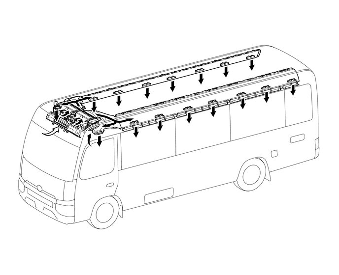
Room Cooler Air Outlet and Airflow
0,0 0,0
false
| *a | The illustrations shown are examples only. | - | - |

|
Recirculation Airflow | 
|
Fresh Airflow |
b.
Front Heater Unit / Boost Ventilator Unit
i.
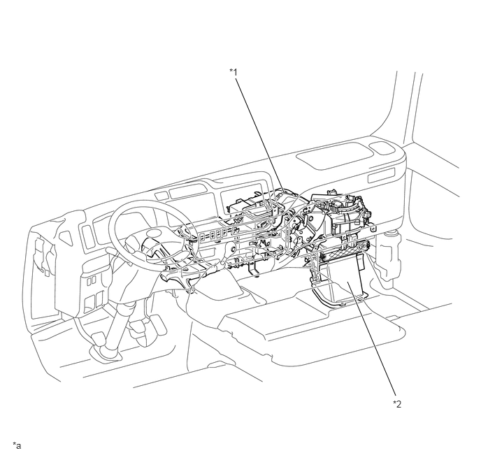
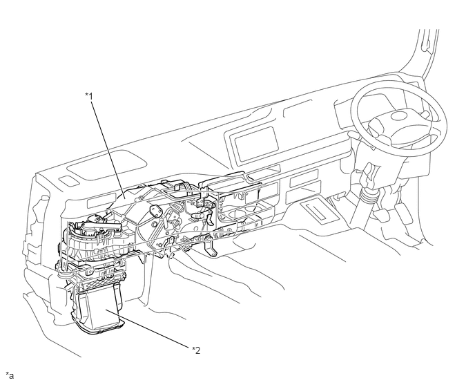
A front heater unit for the manual air conditioner or a boost ventilator unit for the boost vent have been adopted in the instrument panel sub-assembly and provided depending on the specifications.
ii.
A clean air filter (heater air filter) has been adopted and provided depending on the specifications.
Front Heater Unit Parts Location
4.229,2.865 3.51,1.167
true
5.896,5.896 5.177,4.198
true
3.417,0.99 3.729,1.188
0.313,0.198
10
false
*1
5.854,5.938 6.167,6.135
0.313,0.198
10
false
*2
0.188,6.552 0.5,6.75
0.313,0.198
10
false
*a
| *1 | Heater Assembly | *2 | Air Damper Case Assembly |
| *a | The illustrations shown are examples only. | - | - |
Boost Ventilator Unit Parts Location
1.885,3 1.375,1.531
true
2.844,5.24 1.594,4.667
true
1.281,1.365 1.594,1.563
0.313,0.198
10
false
*1
0.083,5.573 0.396,5.771
0.313,0.198
10
false
*a
2.896,5.198 3.208,5.396
0.313,0.198
10
false
*2
| *1 | Boost Ventilator Assembly | *2 | Air Damper Case Assembly |
| *a | The illustrations shown are examples only. | - | - |
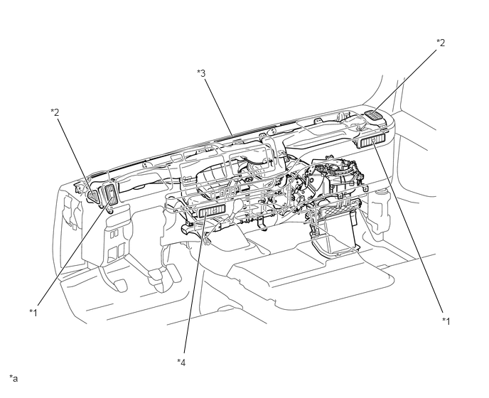
Front Heater Duct Parts Location
2.698,5.177 3.021,3.104
true
0.844,1.74 1.365,2.865
true
0.552,4.479 1.646,2.885
true
3,1.156 3.406,2
true
6.49,4.583 5.458,2.063
true
6.396,0.729 5.458,1.656
true
2.885,0.99 3.198,1.188
0.313,0.198
10
false
*3
0.74,1.563 1.052,1.76
0.313,0.198
10
false
*2
0.427,4.5 0.74,4.698
0.313,0.198
10
false
*1
2.594,5.229 2.906,5.427
0.313,0.198
10
false
*4
6.479,4.625 6.792,4.823
0.313,0.198
10
false
*1
6.396,0.542 6.708,0.74
0.313,0.198
10
false
*2
0.135,5.458 0.448,5.656
0.313,0.198
10
false
*a
| *1 | Side Register | *2 | Side Defroster |
| *3 | Front Defroster | *4 | Center Register |
| *a | The illustrations shown are examples only. | - | - |
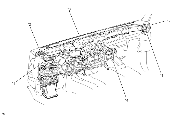
Boost Ventilator Duct Parts Location
0.646,3.313 1.906,2.396
true
1.219,1.104 1.635,2.125
true
2.792,0.458 3.208,1.479
true
6,1.031 6.677,0.844
true
5.833,1.135 6.479,2.958
true
4.427,2.125 5.073,3.948
true
2.719,0.292 3.031,0.49
0.313,0.198
10
false
*3
1.115,0.906 1.427,1.104
0.313,0.198
10
false
*2
0.479,3.302 0.792,3.5
0.313,0.198
10
false
*1
5.031,3.979 5.344,4.177
0.313,0.198
10
false
*4
6.448,2.979 6.76,3.177
0.313,0.198
10
false
*1
6.729,0.771 7.042,0.969
0.313,0.198
10
false
*2
0.063,4.531 0.375,4.729
0.313,0.198
10
false
*a
| *1 | Side Register | *2 | Side Defroster |
| *3 | Front Defroster | *4 | Center Register |
| *a | The illustrations shown are examples only. | - | - |
3.531,2.771 3.938,4.042
3.938,4.042 2.844,2.938
true
2.625,4.094 2.323,2.885
true
0.406,2.719 0.948,2.594
true
1.969,2.188 1.885,1.958
true
3.198,1.958 2.573,1
true
0.354,3.594 0.896,3.24
true
0.229,1.083 0.542,1.281
0.313,0.198
10
false
*1
0.438,2.021 0.75,2.219
0.313,0.198
10
false
*3
2.469,0.813 2.781,1.01
0.313,0.198
10
false
*8
4.385,1.104 4.698,1.302
0.313,0.198
10
false
*2
6.823,1.115 7.135,1.313
0.313,0.198
10
false
*1
6.615,2.052 6.927,2.25
0.313,0.198
10
false
*3
5.417,2.031 5.729,2.229
0.313,0.198
10
false
*4
6.438,3.24 6.75,3.438
0.313,0.198
10
false
*5
3.917,4.063 4.229,4.26
0.313,0.198
10
false
*8
2.573,4.125 2.885,4.323
0.313,0.198
10
false
*7
1.177,4.208 1.49,4.406
0.313,0.198
10
false
*b
1.635,3.208 1.948,3.406
0.313,0.198
10
false
*5
0.208,3.563 0.521,3.76
0.313,0.198
10
false
*6
0.177,3.031 0.49,3.229
0.313,0.198
10
false
*a
0.25,2.656 0.563,2.854
0.313,0.198
10
false
*9
1.792,1.781 2.104,1.979
0.313,0.198
10
false
*7
0.083,4.563 0.396,4.76
0.313,0.198
10
false
*c
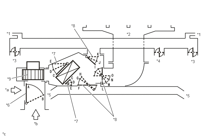
| *1 | Side Defroster | *2 | Front Defroster |
| *3 | Side Register | *4 | Center Register |
| *5 | Footwell Register Duct | *6 | Recirculation / Fresh Air Control Door |
| *7 | Air Mix Control Door | *8 | Mode Control Door |
| *9 | Front Heater Blower Motor (Front Heater Blower Case Sub-assembly) | - | - |
| *a | Recirculation Air | *b | Fresh Air |
| *c | This illustration is a model diagram showing the door positions in each mode. The parts layout and the number of the door in the illustration are different from those of the actual system. | - | - |
| Control Door | Operation Position | Door Position | Operation |
|---|---|---|---|
| Recirculation / Fresh Air Control Door | FRESH | A | Brings in fresh air. |
| RECIRCULATION | B | Recirculates internal air. | |
| Air Mix Control Door | MAX COLD to MAX HOT | E to D to C | Varies the mixture ratio of the cold air and the hot air in order to regulate the temperature continuously from HOT to COLD. |
| Mode Control Door | DEF | F, I, O | Air blows out of the front defroster, side defroster, center register and side register. |
| FOOT/DEF | G, J, N | Air blows out of the front defroster, side defroster, center register, side register and footwell register duct. | |
| FOOT | H, K, M | Air blows out of the center register, side register and footwell register duct. In addition, air blows out slightly from the front defroster and side defroster. | |
| BI-LEVEL | G, J, L | Air blows out of the center register, side register and footwell register duct. In addition, air blows out slightly from the side defroster. | |
| FACE | F, I, L | Air blows out of the side defroster, center register and side register. |
0.375,6.833 4.51,7.156
4.135,0.323
10
false
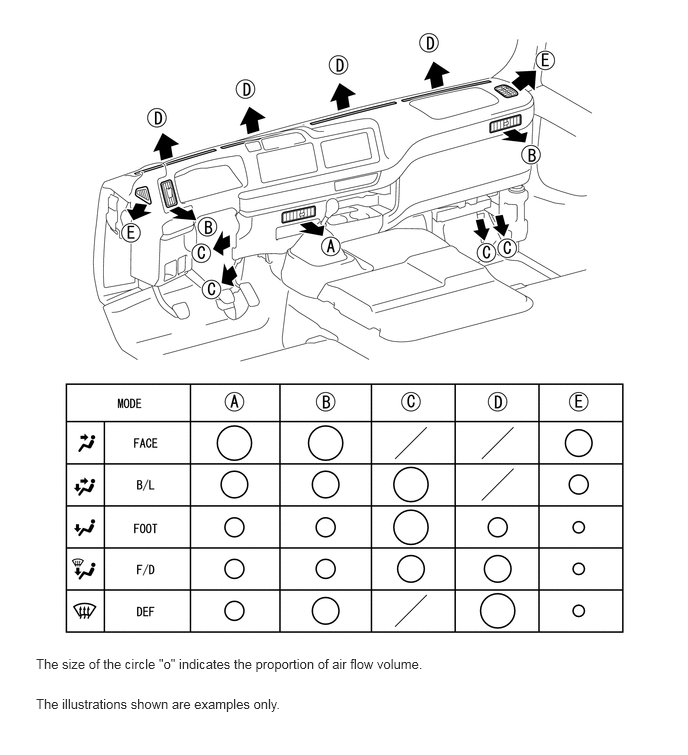
The size of the circle "o" indicates the proportion of air flow volume.
0.375,7.25 4.51,7.573
4.135,0.323
10
false
The illustrations shown are examples only.