A444E AUTOMATIC TRANSMISSION / TRANSAXLE AUTOMATIC TRANSMISSION SYSTEM CONTROL AUTOMATIC TRANSMISSION CONTROL
SYSTEM CONTROL
The electronic control system of the A444E automatic transmission consists of the control functions listed below.
| System | Function |
| Shift Timing Control | The ECT ECU sends current to the solenoid valve S1 and / or S2 based on the signals from each sensor and shifts the gear. |
| Lock-up Timing Control | The ECT ECU sends current to the solenoid valve SL based on signals from each sensor and engages or disengages the lock-up clutch. |
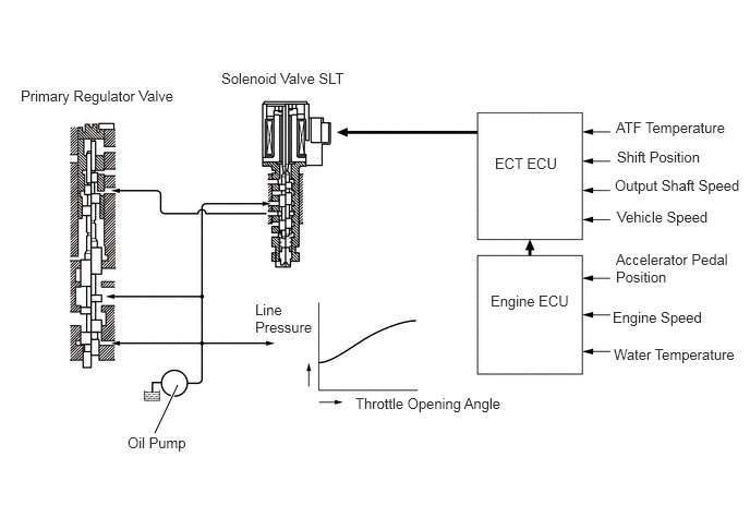
| Line Pressure Control | Actuates the solenoid valve SLT to control the line pressure in accordance with information from the ECT ECU and the operating conditions of the transmission. |
| "N" or "D" Squat Control | When the shift lever is shifted from the "N" to "D" position, the gear is temporarily shifted to the 2nd and then to the 1st to reduce vehicle squat. |
| Engine Torque Control | Temporarily reduces the fuel injection volume to restrict the output torque, thus ensuring the shift feel during upshifting or downshifting. |
| 2nd Start System | Enabling the vehicle to take off in the 2nd gear and thus make it easy to take off on snowy, sandy or muddy terrain. |
| Diagnosis | When the ECT ECU detects a malfunction, the ECT ECU makes a diagnosis and memorizes the failed section. |
| Fail-safe | Even if a malfunction is detected in the sensors or solenoids, the ECT ECU effects fail-safe control to prevent the vehicle's drivability from being affected significantly. |
Line Pressure Control
In order to obtain a predetermined line pressure characteristic according to the each sensor signal, the ECT ECU activates the solenoid valve SLT to regulate the throttle pressure. This makes it possible for the primary regulator valve to precisely and minutely control the line pressure in accordance with the engine output, thus realizing smoother shift characteristics.
FAIL-SAFE
This function minimizes the loss of operability when any abnormality occurs in each sensor or solenoid.
| Malfunction Part | Function |
| ATF Temperature Sensors No. 1 and No. 2 | During a malfunction of the ATF temperature sensors No. 1 and No. 2, the system effects shift control by fixing the ATF temperature at 100°C (196°F). |
| Output Speed Sensor | During an output speed sensor malfunction, shift control is effected through the speedometer signal (SPD1) or engine speed signal (NE). |
| Solenoid Valves S1, S2 and ST | The current to the failed solenoid valve is cut off and control is effected by operating the other solenoid valves. Shift control is effected depending on the failed solenoid as described in the table below. |
| Solenoid Valve SL | During a solenoid valve SL malfunction, the current to the solenoid is stopped. Because this stops lock-up control, then fuel economy decreases. |
| Solenoid Valve SLT | During a solenoid valve SLT malfunction, the current to the solenoid valve is stopped. Because this stops line pressure control, the shift shock increases. However, shifting is effected through normal clutch pressure control. |
| Shift Lever Position | Normal | Solenoid Valve S1 Malfunction | ||||
| Solenoid Valve | Gear | Solenoid Valve | Gear | |||
| S1 | S2 | S1 | S2 | |||
| D | ON | OFF | 1st | X | OFF
↓ ON |
3rd |
| ON | ON | 2nd | X | ON | ||
| OFF | ON | 3rd | X | ON | ||
| OFF | OFF | 4th | X | OFF | 4th | |
| 2 | ON | OFF | 1st | X | OFF
↓ ON |
3rd |
| ON | ON | 2nd | X | ON | ||
| OFF | ON | 3rd | X | ON | ||
| 1 | ON | OFF | 1st | X | OFF | 1st |
| ON | ON | 2nd | X | ON | 2nd | |
| Shift Lever Position | Solenoid Valve S2 Malfunction | Solenoid Valves S1 and S2 Malfunction | ||||
| Solenoid Valve | Gear | Solenoid Valve | Gear | |||
| S1 | S2 | S1 | S2 | |||
| D | ON | X | 1st | X | X | 4th |
| ON
↓ OFF |
X | 4th | X | X | ||
| OFF | X | X | X | |||
| OFF | X | X | X | |||
| 2 | ON | X | 1st | X | X | 3rd |
| ON | X | 3rd | X | X | ||
| OFF | X | X | X | |||
| 1 | ON | X | 1st | X | X | 1st |
| ON | X | X | X | |||
DIAGNOSIS
When the ECT ECU detects a malfunction, the ECT ECU makes a diagnosis and memorizes the failed section. Furthermore, the OD OFF indicator light in the combination meter illuminates or blinks to inform the driver.
At the same time, the DTCs (Diagnosis Trouble Codes) are stored in memory. For details, see the Coaster Repair Manual Supplement.