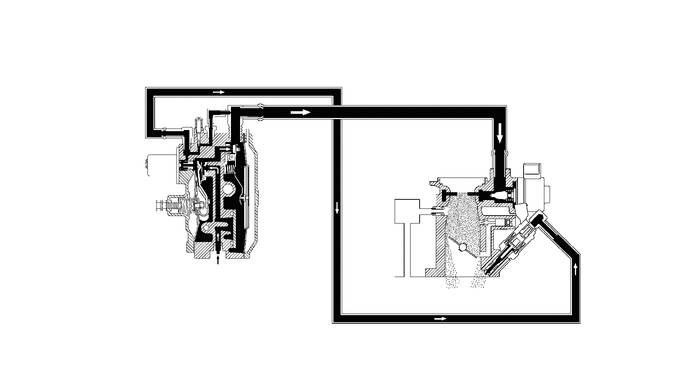
1BZ-FPE ENGINE CONTROL ELECTRONIC CONTROLLED CARBURETOR SYSTEM DETAILS LPG REGULATOR AND CARBURETOR
CONSTRUCTION
General
In the 1BZ-FPE engine, fuel is supplied in the following manner: the LPG regulator atomizes the fuel from the fuel tank, and the LPG carburetor mixes the fuel with the intake air.
An LPG injector and an air-fuel ratio control motor have been adopted to enable the engine ECU to regulate the fuel. As a result, the precision of the air-fuel ratio control has been improved.
A slow lock solenoid valve has been provided in the LPG regulator to open and close the slow passage.
An ISCV (Idle Speed Control Valve) has been provided separately from the LPG carburetor to regulate the engine speed at idle.
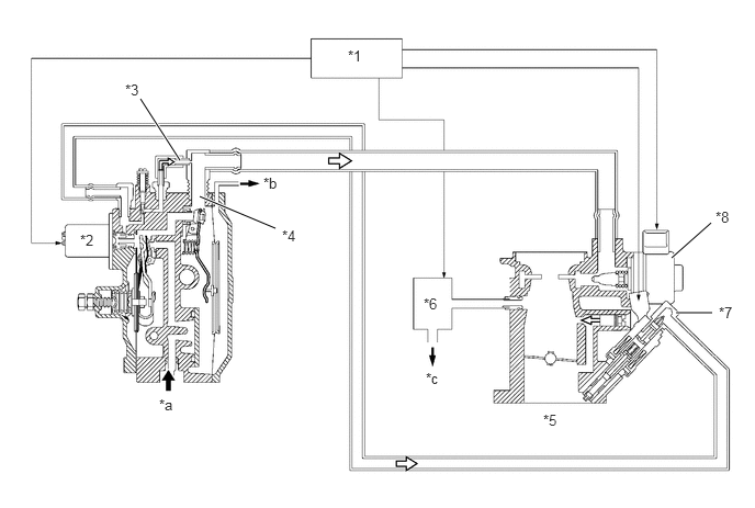
| *1 | Engine ECU | *2 | Slow Lock Solenoid Valve |
| *3 | Slow Passage | *4 | Main Passage |
| *5 | LPG Carburetor | *6 | ISCV |
| *7 | LPG Injector | *8 | Air Fuel Ratio Control Motor |
| *a | From Fuel Tank | *b | To Air Cleaner |
| *c | To Intake Manifold | - | - |
LPG Regulator
The LPG regulator consists of a pre-heater chamber, primary decompression chamber, and secondary decompression chamber.
The fuel that flows into the LPG regulator becomes heated by the engine coolant in the pre-heater chamber. The fuel's vapor pressure pushes open the elastic face valve (first). Then, the pressure enters the primary decompression chamber where it becomes decompressed and atomized.
When the pressure in the primary decompression chamber reachs a prescribed value, the first diaphragm closes the elastic face valve (first), in order to keep the pressureconstant.
The vacuum of the LPG carburetor acts in the secondary decompression chamber via the main passage. This create a vaccum in the secondary decompression chamber, causing the second diaphragm to push the second valve lever, which opens the elastic face valve (second). Thus, thefuel flows into the secondary decompression chamber.
When the pressure in the secondary decompression chamber approaches the atmospheric pressure, the elastic face valve (second) closes in order to maintain the secondary decompression chamber below the atomspheric pressure.
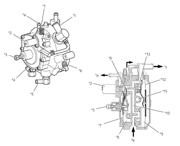
| *1 | Idle Adjust Screw | *2 | Slow Lock Solenoid Valve |
| *3 | First Regulator Screw | *4 | Water Outlet |
| *5 | Water Inlet | *6 | Elastic Face Valve (First) |
| *7 | First Diagphragm | *8 | Primary Decompression Chamber |
| *9 | Secondary Decompression Chamber | *10 | Pre-heater Chamber |
| *11 | Water Passage | *12 | Second Diagphragm |
| *13 | Elastic Face Valve (Second) | - | - |
| *a | To LPG Injector | *b | From LPG Pre-heater |
| *c | To LPG Carburetor | - | - |
LPG Carburetor
The LPG carburetor consists of an air-fuel ratio control motor and LPG injector.
The fuel that is sent by the LPG regulator passes through the venturi area and is then fed into the intake manifold.
An air-fuel ratio control motor is provided mid-stream of the fuel passage. The needle valve at the tip moves in accordance with the signals from the engine ECU to vary the flow volume of the fuel.
The LPG injector injects auxiliary fuel in order to regulate the air-fuel ratio.
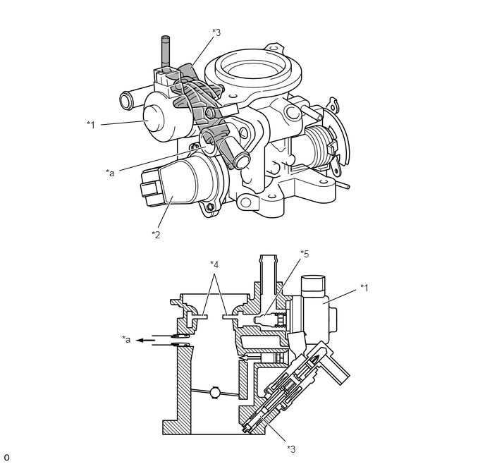
| *1 | Air Fuel Ratio Control Motor | *2 | Throttle Position Sensor |
| *3 | LPG Injector | *4 | Venturi |
| *5 | Needle Valve | - | - |
| *a | To ISCV | - | - |
OPERATION
During idling or light load driving
When the venturi vacuum pressure in the carburetor is low, most of the fuel is fed through the slow passage. Then, the LPG injector injects the amount of fuel that lacks in relation to the stoichiometric air-fuel ratio in order to regulate the air-fuel ratio.
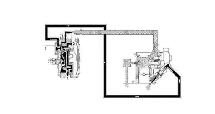
Other driving conditions
When the venturi vacuum pressure becomes high, the fuel is fed through the main and slow passages. Under medium-load conditions, most of the fuel is fed through the main passage. Then, to regulate the air-fuel ratio, the LPG injector injects the amount of fuel that is lacking in relation to the stoichiometric air-fuel ratio. The fuel flow volume of the LPG injector becomes fixed under heavy-load conditions, and the air-fuel ratio control motor varies the flow volume of the main passage in order to regulate the overall injection volume.