BRAKE CONTROL / DYNAMIC CONTROL SYSTEMS BRAKE CONTROL SYSTEM(w/ VSC) CONTROL BRAKE CONTROL
FUNCTION OF MAIN COMPONENTS
| Component | Function | |
|---|---|---|
| Speed Sensors | Detect the wheel speed of each of the 4 wheels. | |
| Stop Light Switch Assembly | Detect the brake pedal depressing signal. | |
| Back Up Light Switch Assembly | Detects the reverse position. | |
| Vacuum Sensor Assembly | The pressure inside the brake booster assembly is detected. | |
| Vacuum Warning Switch Assembly | Detect the lowering of the brake negative pressure. | |
| Brake Pedal Sub-assembly | Brake Pedal Load Sensing Switch | The pressing force of the brake pedal is detected. |
| Brake Master Cylinder Reservoir Assembly | Brake Fluid Level Warning Switch | Detect the brake fluid level. |
| VSC OFF Switch | Enables the driver to select the "Normal Mode", "TRC-OFF Mode" or "VSC-OFF Mode". | |
| Brake Actuator Assembly | Solenoid Valves | Changes the fluid path based on the signals from the skid control ECU during the operation of the brake control system functions, in order to control the fluid pressure that is applied to the wheel cylinders. |
| Solenoid Relay | Supplies power to the solenoid valves. | |
| Motor Relay | Supplies power to the pump motor. | |
| Motor Cut Relay | Cuts the power to the pump motor in the brake actuator. | |
| Master Cylinder Pressure Sensor | Assembled in the brake actuator, detects the master cylinder pressure. | |
| Skid Control ECU | Judges the vehicle driving condition based on the signals from each sensor, and sends the brake control signals to the brake actuator. | |
| Pump Motor | Drivers the pumps inside the brake actuator. | |
| Spiral Cable with Sensor Sub-assembly | Steering Angle Sensor | Detects the direction and angle of the steering wheel. |
| Airbag ECU Assembly | Yawrate and Deceleration Sensor | ·
The yawrate sensor detects the vehicle's yaw rate. ·
The deceleration sensor detects the vehicle's longitudinal and lateral acceleration and deceleration. |
| Network Gateway ECU | Relays a signal of CAN communication. | |
| Combination Meter Assembly | Brake System Warning Light | ·
Illuminates to alert the driver when the skid control ECU detects a malfunction in the EBD or brake system. ·
Illuminates to alert the driver when the brake fluid level is low, when the pressure inside the vacuum tank is low. |
| ABS Warning Light | Illuminates to alert the driver when the skid control ECU detects a malfunction in the ABS. | |
| Slip Indicator Light | ·
Blinks to inform the driver when the TRC or VSC is operational. ·
Illuminates to alert the driver when the skid control ECU detects a malfunction in the TRC or VSC. |
|
| VSC OFF Indicator Light | Illuminates to inform the driver of the VSC-OFF mode. | |
| TRC OFF Indicator Light | Illuminates to inform the driver of the VSC-OFF mode or TRC-OFF mode. | |
| Buzzer | Emits a warning sound to alert the driver when the brake fluid level is low, when the pressure inside the vacuum tank is low. | |
| ECM | ·
Sends the throttle position signal, accelerator pedal position signal and engine signal etc., to the skid control ECU. ·
Based on the signals received from the skid control ECU, controls the engine output. |
|
FUNCTION
VSC OFF Switch
The operation of the VSC and TRC functions can be stopped by the VSC OFF switch. While the vehicle is running off the shoulder of the road or running on the dirt road, the engine output control is stopped to maintain drive torque.
The VSC OFF switch can select the 3 modes (Normal Mode, TRC-OFF Mode and VSC-OFF Mode). When the VSC OFF switch is pressed briefly, TRC OFF Mode is entered and the TRC function will be disabled. When the VSC OFF switch is pressed and held for 3 seconds or more, VSC-OFF Mode is entered and the TRC and VSC functions will be disabled.
After the ignition switch is turned off in TRC-OFF Mode or VSC-OFF Mode, turning the ignition switch to on again selects the Normal Mode. The system also enters Normal Mode automatically when the vehicle speed increases in TRC-OFF Mode.
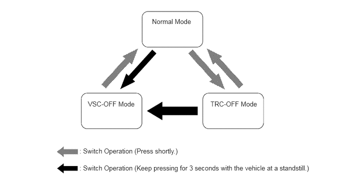
The operations of the brake control functions in each mode are as follows:
| Mode | Brake Control Function | Combination Meter Assembly | ||
|---|---|---|---|---|
| TRC | VSC | VSC OFF Indicator Light | TRC OFF Indicator Light | |
|
○: Controllable x: Not controllable *: The control is effected during braking or while the yaw rate is large. |
||||
| Normal Mode | ○ | ○ | Light Off | Light Off |
| TRC-OFF Mode | x | ○ | Light Off | Light On |
| VSC-OFF Mode | x | x* | Light On | Light On |
- NOTICE:
-
The TRC and VSC functions control brake hydraulic pressure and engine output to ensure vehicle stability. Therefore, operate the VSC OFF switch (stop the operation of the TRC and VSC functions) only when it is necessary.
FAIL-SAFE
If a failure occurs in the skid control ECU, sensors, or brake actuator assembly, the system continues performing brake control by excluding the failed area and using only the areas that are operating normally.
DIAGNOSIS
If the skid control ECU detects a malfunction in the brake control system, the warning lights or indicator light illuminate. At the same time, a Diagnostic Trouble Code (DTC) is stored in the memory of the skid control ECU.
This system has a sensor signal check (test mode) function.
For details of DTCs and check function, refer to the Repair Manual.