INTERIOR PANELS / TRIM INTERIOR GENERAL GENERAL
OUTLINE
General
A driver area to safely convey passengers and a comfortable passenger cabin area have been created based on the design concept of "Function and Hospitality" for a welcoming, bright, and high-quality interior space.
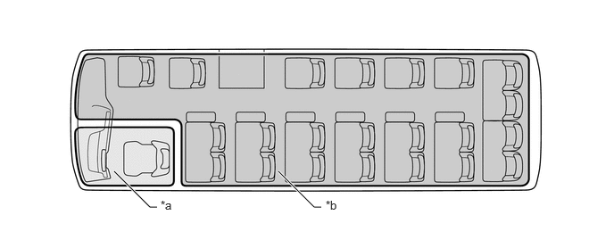
| *a | Driver Area | *b | Passenger Cabin Area |
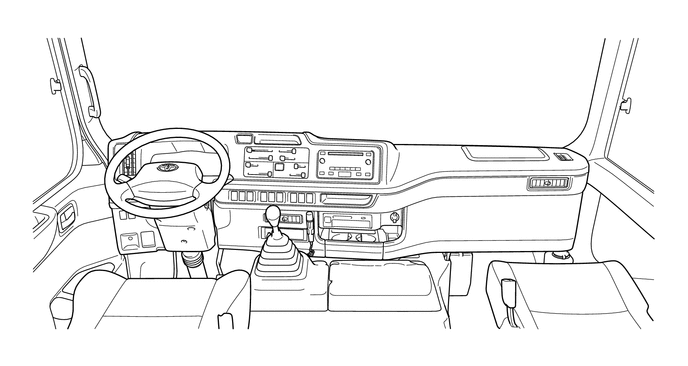
Driver Area
The optimal functional layout for professional drivers makes the driver area a functionally specialized cockpit. Furthermore, the simple yet modern shape and excellent view from the interior create a spacious area.
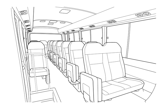
Passenger Cabin Area
The passenger cabin area provides a sense of freedom and a simple yet modern, high-quality space as soon as the passengers board. Once seated, the pleasant passengers space provides a sense of satisfaction.
MAIN FEATURES
Instrument Panel Sub-assembly
The instrument panel sub-assembly has been designed to leave a refined impression with a feeling of a change for the better.
The functions of the instrument panel sub-assembly are arranged facing the driver's side. Concentrating the functions in a reachable area improves usability. Furthermore, grouping the function switches provides a layout that considers usability as the passengers come and go.
Unifying the meter hood with the instrument panel sub-assembly improves the feeling of quality.
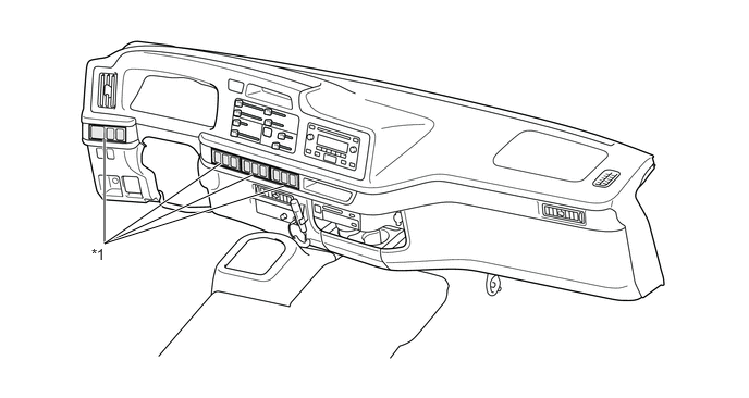
| *1 | Grouping of Function Switch | - | - |
Storage Space
The arrangement of multiple storage spaces in the instrument panel sub-assembly improves storage and convenience.
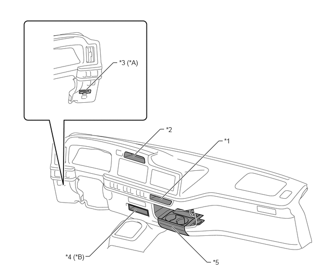
| *A | RHD Models | *B | Models with Accessory Compartment in Front of Shift Lever (Stereo Opening Cover) |
| *1 | Center Accessory Compartment | *2 | Top Accessory Compartment |
| *3 | Card Holder (Instrument Panel Hole Cover) | *4 | Accessory Compartment in Front of Shift Lever (Stereo Opening Cover) |
| *5 | Large Bottom Center Tray (Instrument Panel Under Tray Sub-assembly) | - | - |
Center Accessory Compartment
The center accessory compartment has an open layout for easy placement of a mobile phone, music player, and other small object in consideration of usability and convenience. Placement of the center accessory compartment near No. 1 power outlet socket assembly makes it possible to store a mobile phone, music player, or other device while charging it.
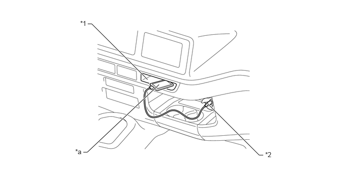
| *1 | Center Accessory Compartment | *2 | No. 1 Power Outlet Socket Assembly |
| *a | Mobile Phone, Music Player, or Other Device | - | - |
Large Bottom Center Tray (Instrument Panel Under Tray Sub-assembly)
A large bottom center tray (instrument panel under tray sub-assembly) of large-capacity has been adopted for an improves storage. In addition, like the center accessory compartment, the tray is located near No. 1 power outlet socket assembly, which makes it possible to store a mobile phone, music player, or other device while charging it.
For convenience, the large bottom center tray (instrument panel under tray sub-assembly) can be pulled out to hold up a 500 mL bottle or other object.
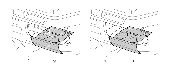
| *A | Models with Tachograph Assembly | *B | Models without Tachograph Assembly |
| *1 | Large Bottom Center Tray (Instrument Panel Under Tray Sub-assembly) | - | - |
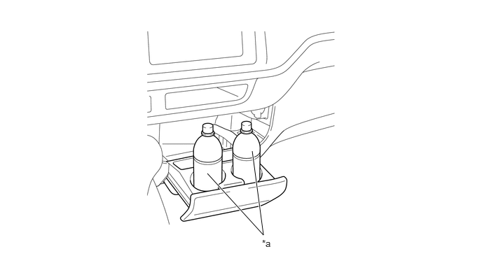
| *a | 500 mL Bottle | - | - |
Clock
A digital clock assembly with a Liquid Crystal Display (LCD) has been adopted and provided depending on the specifications.
The clock assembly projects using Light Emitting Diodes (LED) for power saving and longer life.
The attachment position is the inner rear view mirror assembly section.
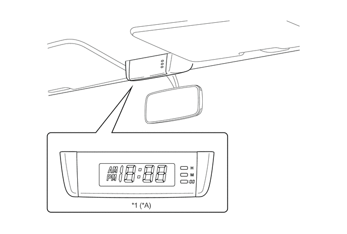
| *A | Models with Clock Assembly | - | - |
| *1 | Clock Assembly | - | - |
| Display Range | 1:00 - 12:59 (12-hour Display Method) |
| Precision [Seconds/Day] | +/-0.5 (DC13 V, at 20 degrees) |
| Rated Voltage [V] | DC12 |
Side Design
Each pillar is shaped to make the opening of the window area appear wide, which offers a sense of spaciousness. (1)
The upper section of the inside trim is shaped for easy placement of the elbow and surface processed for improved comfort. (2)
The inside trim section has a concave surface that fits around the waist of the passengers to emphasize the width. (3)
The shape and color scheme of the floor mat that spreads to the side of the vehicle ensures foot space and considers cleanliness. (4)
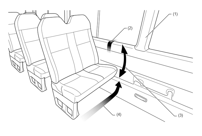
A inside trim cover has been adopted for the upper section of the inside trim on some specification models to improve the feel of the material.
Pillar garnish has been adopted for each pillar to improve marketability and provided depending on the specifications.
Each pillar shape is optimized to expand the passenger cabin space and reduce the feeling of pressure when sitting in a window seat.
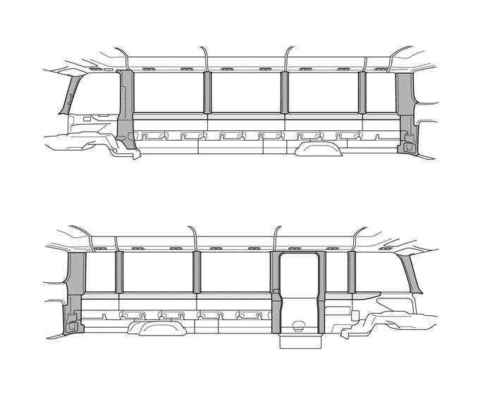

|
Pillar Garnish Adopted Section | 
|
Inside Trim Cover Adopted Section |
Door Trim
A bottle holder that can store a 1.5 L bottle and a front door pocket that can store objects like a A4 sized binder has been provided for the front door trim board sub-assembly.
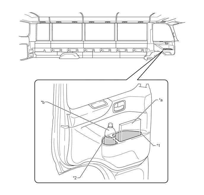
| *1 | Front Door Pocket | *2 | Bottle Holder |
| *a | A4 Sized Binder | *b | 1.5 L Bottle |
Roof Design
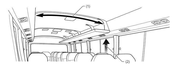
The structure of the roof emphasizes wideness to provide a spacious overhead area. (1)
Setting the top end of the side glass in a high location ensures spaciousness and a good view. (2)
A formed ceiling using non-woven fabric in the cover of the roof headlining assembly and No. 6 roof headlining has been adopted.
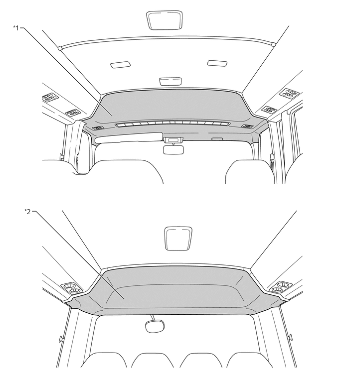
| *1 | Roof Headlining Assembly | *2 | No. 6 Roof Headlining |
A knob shape that can be gripped securely has been adopted for No. 1 air outlet register assembly to ensure high operability.
A visor assembly (driver side) has been adopted in the roof section on the driver's side. Furthermore, a card holder has been adopted in the visor assembly (driver side) of some specification models in consideration of usability.
A visor assembly (front passenger side) has been adopted in the roof section on the front passenger's side and provided depending on the specifications.
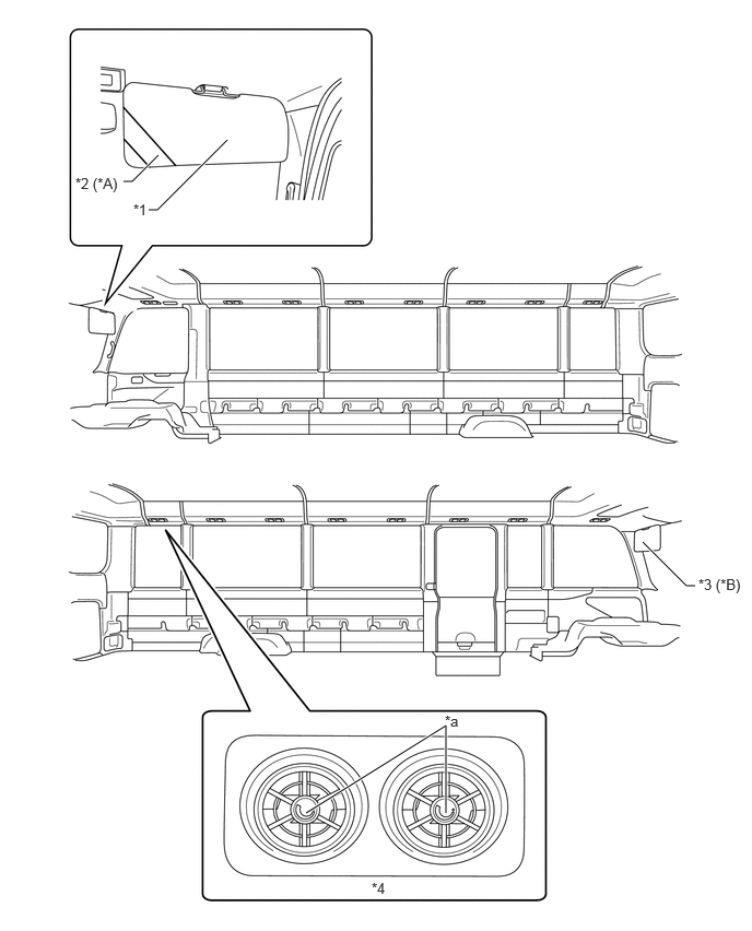
| *A | Models with Card Holder | *B | Models with Visor Assembly (Front Passenger Side) |
| *1 | Visor Assembly (Driver Side) | *2 | Card Holder |
| *3 | Visor Assembly (Front Passenger Side) | *4 | No. 1 Air Outlet Register Assembly |
| *a | Knob | - | - |
A tray type luggage rack (room rack assembly) has been adopted and provided depending on the specifications.
The luggage rack (room rack assembly) ensures space from the interior ceiling surface to improve storage. Furthermore, allocation of the luggage rack (room rack assembly) is optimized in consideration of boarding and alighting.
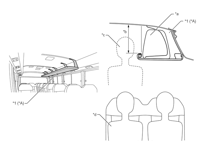
| *A | Models with Luggage Rack (Room Rack Assembly) | - | - |
| *1 | Luggage Rack (Room Rack Assembly) | - | - |
| *a | Luggage | *b | Provision of Space |
| *c | While Standing | *d | While Sitting |
Floor and Rear Design
A slip resistant material, shape and surface processing have been adopted for the center step (center door step mat plate) and floor mat in consideration of boarding and alighting. Furthermore, the center step (center door step mat plate) of some specification models matches the color and pattern of the floor mat to widen the look of the floor surface and provide a modern design suitable for an entrance to welcome passengers.
The depth of the center door step has been expanded to improve boarding and alighting.
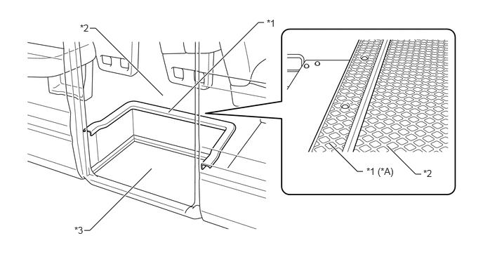
| *A | Models with Center Step (Center Door Step Mat Plate) of the Same Color and Pattern Type as the Floor Mat | - | - |
| *1 | Center Step (Center Door Step Mat Plate) | *2 | Floor Mat |
| *3 | Center Door Step | - | - |
Vehicles equipped with rear sub seats have been adopted the same color as the inside trim color on the bottom surface of the rear sub seat to visually guide passengers to seats.
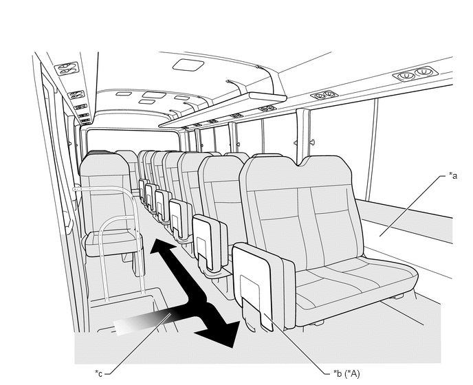
| *A | Models with Rear Sub Seat | - | - |
| *a | Inside Trim Section | *b | Bottom Surface of Rear Sub Seat |
| *c | Passenger Cabin Guidance Lines | - | - |
To ensure foot space, a foot rest has been adopted on the floor of some passenger seats and provided depending on the specifications.
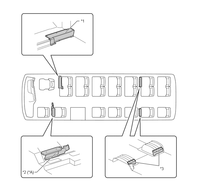
| *A | Models with Foot Rest (No. 2 Footrest Sub-assembly) | - | - |
| *1 | Foot Rest (Front Floor Rear Upper Side Panel) | *2 | Foot Rest (No. 2 Footrest Sub-assembly) |
| *3 | Foot Rest (Rear Footrest Plate) | - | - |
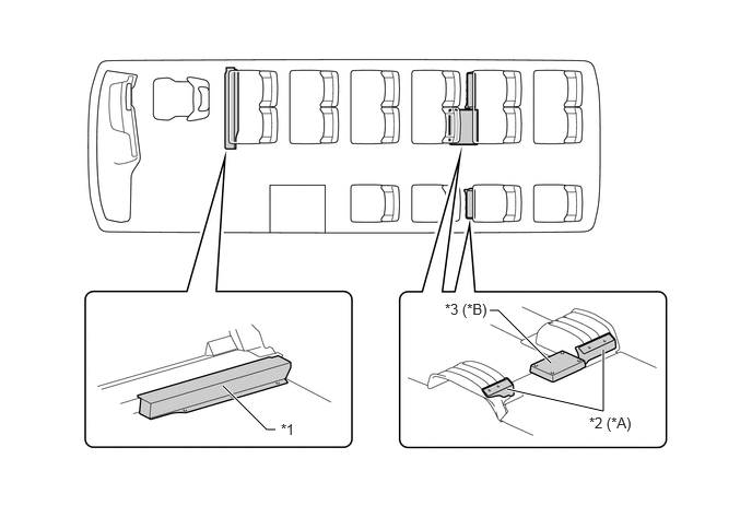
| *A | Models with Foot Rest (Rear Footrest Plate) | *B | Models with Foot Rest (Footrest Panel) |
| *1 | Foot Rest (Footrest Panel Sub-assembly) | *2 | Foot Rest (Rear Footrest Plate) |
| *3 | Foot Rest (Footrest Panel) | - | - |
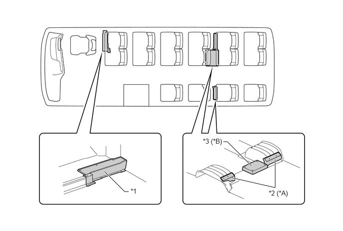
| *A | Models with Foot Rest (Rear Footrest Plate) | *B | Models with Foot Rest (Footrest Panel) |
| *1 | Foot Rest (Front Floor Rear Upper Side Panel) | *2 | Foot Rest (Rear Footrest Plate) |
| *3 | Foot Rest (Footrest Panel) | - | - |
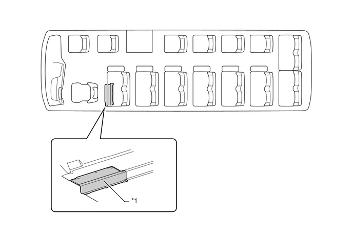
| *1 | Foot Rest (Front Floor Rear Upper Side Panel) | - | - |
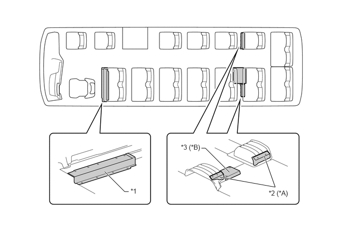
| *A | Models with Foot Rest (Rear Footrest Plate) | *B | Models with Foot Rest (Footrest Panel) |
| *1 | Foot Rest (Front Floor Rear Upper Side Panel) | *2 | Foot Rest (Rear Footrest Plate) |
| *3 | Foot Rest (Footrest Panel) | - | - |