N04C-VQ ENGINE CONTROL ECD SYSTEM CONTROL TURBOCHARGER CONTROL
FUNCTION
The ECM controls the nozzle vane position using the turbo motor driver, in order to obtain the calculated target turbo pressure appropriate to the engine operating conditions.
The turbo motor driver detects the actual nozzle vane position and provides feedback to the ECM. The ECM calculates the optimal nozzle vane position in accordance with the driving conditions (engine speed, injection volume, atmospheric pressure and water temperature, etc.), and sends a target nozzle vane position signal to the turbo motor driver. The turbo motor driver controls the nozzle vane position in accordance with this signal and the actual nozzle vane position.
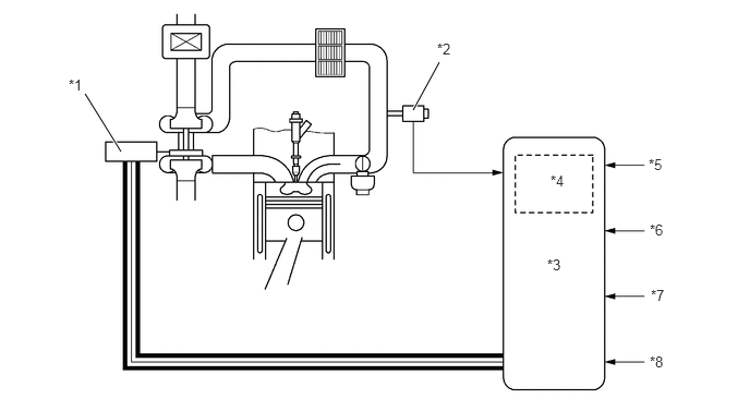
| *1 | Turbo Motor Driver and DC Motor (Nozzle Vane Position Control) | *2 | Turbo Pressure Sensor |
| *3 | ECM | *4 | Atmospheric Pressure Sensor |
| *5 | Crankshaft Position Sensor | *6 | Injector Assembly |
| *7 | Engine Coolant Temperature Sensor | *8 | Intake Air Temperature Sensor |

|
CAN | - | - |
OPERATION
In Low Speed Range
When the engine is running in a low speed range, the DC motor presses down the linkage with a signal from the turbo motor driver. The tip of the linkage rotates the unison ring counterclockwise through a drive arm.
The unison ring contains a driven arm, which is placed through the cutout portion of the unison ring. This driven arm also moves in the direction of the rotation of the unison ring. The fulcrum of the driven arm is an axis that is integrated with the nozzle vane behind the plate. When the driven arm moves counterclockwise, the nozzle vane moves toward the closing direction. This results in an increase in the velocity of the exhaust gas flowing to the turbine, as well as the speed of the turbine. As a result, torque is improved when the engine is running at low speeds.
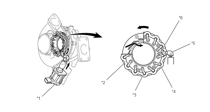
| *1 | Turbo Motor Driver and DC Motor | *2 | Unison Ring |
| *3 | Cutout Portion | *4 | Driven Arm |
| *5 | Linkage | *6 | Drive Arm |
In Medium-to-High Speed Range
When the engine is running in a medium-to-high speed range, the DC motor pulls up the linkage with a signal from the turbo motor driver. With this, the driven arm moves clockwise and this opens the nozzle vane and maintains the specified supercharging pressure. Thus, the back pressure is lowered and the output and fuel consumption are improved.
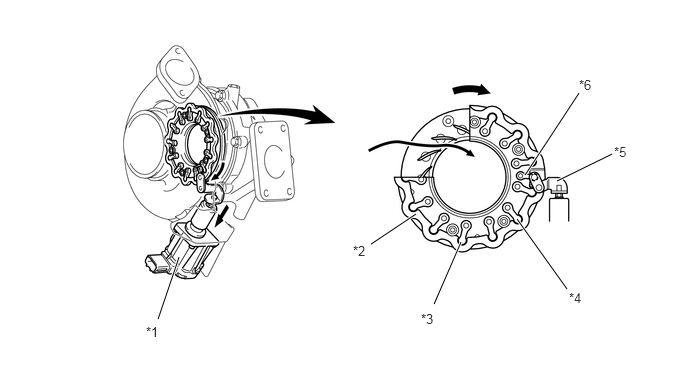
| *1 | Turbo Motor Driver and DC Motor | *2 | Unison Ring |
| *3 | Cutout Portion | *4 | Driven Arm |
| *5 | Linkage | *6 | Drive Arm |