N04C-WA ENGINE MECHANICAL ENGINE UNIT DETAILS CYLINDER HEAD
CONSTRUCTION
A cylinder head made of high-strength cast iron is used. The thickness of the walls and the layout of the water jacket have been optimized to achieve well-balanced rigidity and cooling performance. Two intake valves and two exhaust valves have been provided for each cylinder, and the shape of the ports has been optimized.
Cross-flow type intake ports that consist of two different shapes are used to produce an optimal swirl in order to achieve high charging efficiency and exhaust efficiency.
Valve guides made of a sintered material that provides good oil retention are used in order to ensure seizure resistance and wear resistance. Furthermore, the amount of oil leakage through the valve stem oil seal has been minimized to achieve low oil consumption and exhaust emissions.
A steel laminate type cylinder head gasket is used to achieve high sealing performance and heat resistance.
A No. 2 cylinder head cover made of aluminum alloy is used for weight reduction.
A cylinder head cover gasket made of a highly heat-resistant and oil-resistant fluorine-contained rubber is used to ensure reliability.
The No. 2 cylinder head cover sub-assembly is bolted in two locations in the center to achieve a reduced number of parts and high serviceability.
The No. 2 cylinder head cover sub-assembly is equipped with an impactor type oil separator.
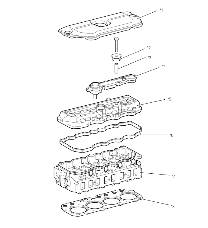
| *1 | No. 1 Engine Cover Sub-assembly | *2 | Cylinder Head Cover Cushion |
| *3 | Cylinder Head Cover Spacer | *4 | Oil Separator Assembly |
| *5 | No. 2 Cylinder Head Cover Sub-assembly | *6 | Cylinder Head Cover Gasket |
| *7 | Cylinder Head Sub-assembly | *8 | Cylinder Head Gasket |
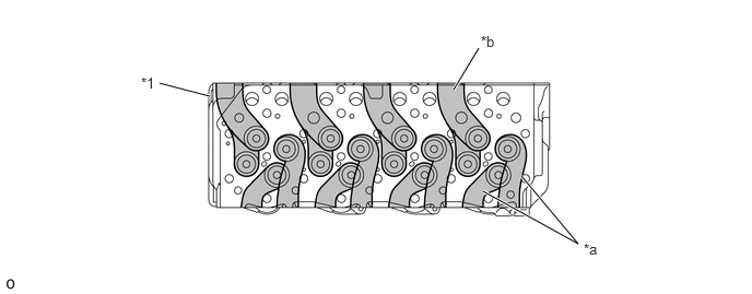
| *1 | Cylinder Head Sub-assembly | - | - |
| *a | Intake Ports | *b | Exhaust Port |