N04C-WA ENGINE CONTROL ECD SYSTEM CONTROL SUPPLY PUMP CONTROL
CONSTRUCTION
The drive force of the pump outputs in the following order: the crankshaft, the idle gears, the gear that is attached to the front of the pump, and the ring cam.
The injection or supply pump assembly consists of four portions: a pump body to pump pressurized fuel, a discharge check valve to regulate the fuel flow rate, a suction control valve to regulate the fuel pressure at the inlet to the inhale check valve, and a feed pump to supply fuel to the pump body. The injection or supply pump assembly draws an appropriate amount of fuel and feeds pressurized fuel into the common rail assembly.
The eccentric cam alternately moves two plungers via the ring cam.
The two plungers are horizontally opposed, so when one plunger is in a suction stroke, the other is in a pumping stroke. The two plungers repeat these strokes in order to ensure a constant and stable delivery of fuel.
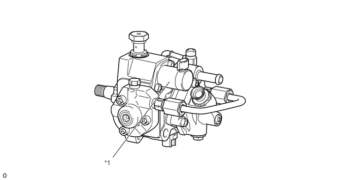
| *1 | SCV (Suction Control Valve) | - | - |
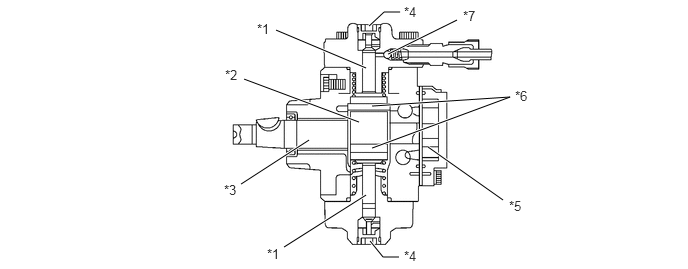
| *1 | Plunger | *2 | Eccentric Cam |
| *3 | Eccentric Camshaft | *4 | Inhale Check Valve |
| *5 | Feed Pump | *6 | Ring Cam |
| *7 | Discharge Check Valve | - | - |
The ECM determines the target fuel pressure based on the load condition.
The ECM adjusts the SCV opening angle by the duty control function to reach the target fuel pressure.
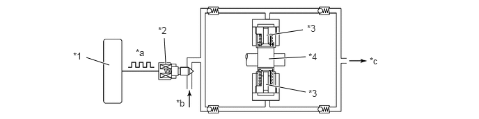
| *1 | ECM | *2 | SCV |
| *3 | Plunger | *4 | Cam |
| *a | Duty Control | *b | Fuel (From Fuel Tank) |
| *c | Fuel (To Common Rail Assembly) | - | - |
OPERATION
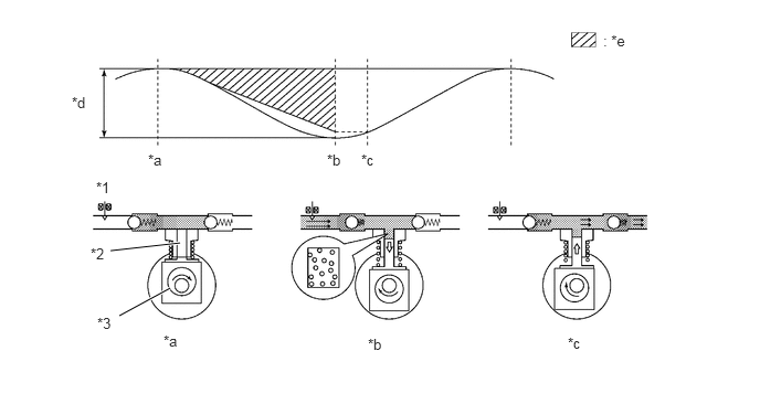
Small Opening of Suction Control Valve
When the opening of the suction control valve is small, the fuel suction passage narrows and slows down the fuel flow.
Even if the plunger reaches its maximum stroke, the volume of fuel drawn in by the plunger becomes restricted because the fuel suction passage is restricted. (See "b" in the diagram.)
The supply pump discharges fuel when the cam pushes the plunger upward and the fuel discharge pressure becomes higher than the fuel pressure in the common rail assembly. (See "c" in the diagram.)
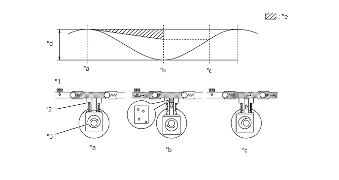
| *1 | SCV | *2 | Plunger |
| *3 | Cam | - | - |
| *a | Plunger Top-Dead-Center | *b | Plunger Bottom-Dead-Center |
| *c | Compression Starting Point | *d | Plunger Stroke |
| *e | Fuel Suction Volume | - | - |
Large Opening of Suction Control Valve
When the opening of the suction control valve is large, the fuel suction passage widens and facilitates the fuel flow.
When the plunger reaches its maximum stroke, the plunger draws an ample volume of fuel because the fuel suction passage is not restricted. (See "b" in the diagram.)
The injection or supply pump assembly discharges fuel when the cam pushes the plunger upward and the fuel discharge pressure becomes higher than the fuel pressure in the common rail assembly. (See "c" in the diagram.)
| *1 | SCV | *2 | Plunger |
| *3 | Cam | - | - |
| *a | Plunger Top-Dead-Center | *b | Plunger Bottom-Dead-Center |
| *c | Compression Starting Point | *d | Plunger Stroke |
| *e | Fuel Suction Volume | - | - |