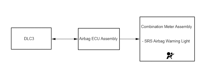
SUPPLEMENTAL RESTRAINT SYSTEMS AIRBAG SYSTEM CONTROL AIRBAG CONTROL
FUNCTION OF MAIN COMPONENTS
The SRS airbag system mainly consists of the parts listed in the table below.
| Components | Function |
|---|---|
|
*1: Models with SRS front passenger airbag *2: Models with CAN communication compatible airbag ECU assembly |
|
| Spiral Cable with Sensor Sub-assembly | Inputs the signals from the airbag ECU assembly and outputs it to the SRS driver airbag (horn button assembly). |
| SRS Driver Airbag (Horn Button Assembly) | These consist of an inflator, a bag, and so on. The inflator deploys gas in accordance with an expansion signal from the airbag ECU assembly and deploys the bag. |
| SRS Front Passenger Airbag (Instrument Panel Passenger Airbag Assembly)*1 | |
| Front Seat Outer Belt Assembly (Driver Side) | The front seat outer belt assemblies are used to help reduce impact to the occupants. |
| Front Seat Outer Belt Assembly (Front Passenger Side)*1 | |
| Front Airbag Sensor | Based on the deceleration of the vehicle during a frontal collision, a distortion is created in the sensor and converted into an electrical signal. |
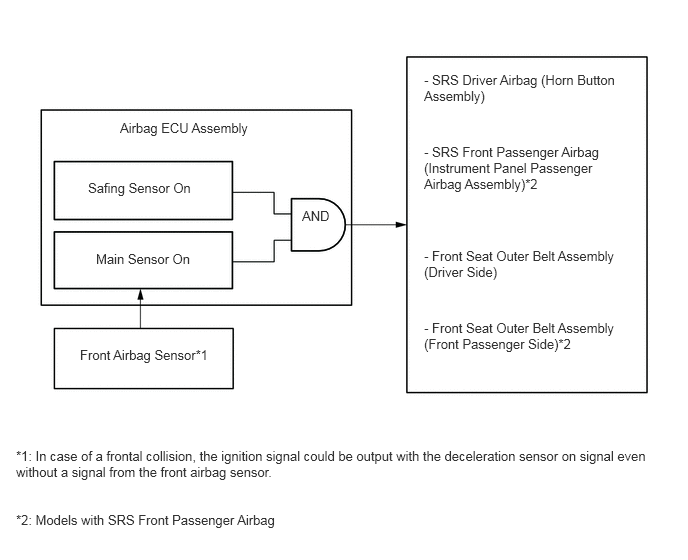
| Airbag ECU Assembly | The airbag ECU assembly receives signals from the deceleration sensor and safing sensor built into the airbag ECU assembly and the front airbag sensor, determines whether the driver airbag, front passenger airbag*1 and front seat belt pretensioners should be activated, and diagnoses system malfunctions. |
| Network Gateway ECU*2 | Relays the signal between the CAN communication. |
| Translate ECU Assembly*2 | Sends airbag activation signal to the ECM via network gateway ECU. |
| Combination Meter Assembly | The SRS airbag warning light turns on to alert the driver when the airbag ECU assembly detects a malfunction in the airbag system. |
| ECM*2 | Stops the fuel pump when both of the SRS airbags have deployed. |
OPERATING CONDITION
Ignition Condition
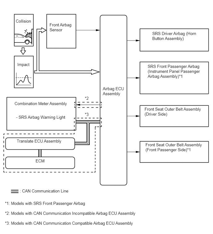
Deceleration sensors used for the airbag system are installed on various parts on the vehicle and calculate the deceleration rate of each part during a collision.
Depending on the situation, the airbag ECU assembly sends a deployment signal to each airbag based on the information from each sensor.
Frontal collision signals are produced based on the information from the airbag ECU assembly and front airbag sensor.
SYSTEM CONTROL
Airbag for Frontal Collision
For frontal collisions, there are 2 airbags and 2 seat belt pretensioners: the SRS driver airbag (horn button assembly), SRS front passenger airbag (instrument panel passenger airbag assembly)*, front seat outer belt assembly (driver side), and front seat outer belt assembly (front passenger side)*. The deployment of the airbags and the activation of the pretensioners occur simultaneously.
*: Models with SRS front passenger airbag
Primary Check Illumination Control
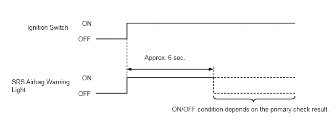
After the ignition switch is on (IG), the airbag ECU assembly illuminates the SRS airbag warning light in the combination meter assembly for approximately 6 seconds and conducts the primary check. During the primary check, the ignition of airbags is prohibited and a diagnosis of the airbag ECU assembly is performed. If trouble is detected during the primary check, the SRS airbag warning light remains on even after the 6 seconds have elapsed. See the illustration below.
DIAGNOSIS
If the airbag ECU assembly detects a malfunction in the SRS airbag system, the airbag ECU assembly stores the malfunction data in memory, in addition to illuminating the SRS airbag warning light.
If the SRS airbag deploys, the airbag ECU assembly will turn on the SRS airbag warning light. However, different from the ordinary diagnosis function, a DTC will not be stored. The SRS airbag warning light cannot be turned off. It is necessary to replace the airbag ECU assembly with a new one.
The 5-digit DTC can be read after connecting the Grobal TechStream (GTS) to the DLC3. For details, refer to the repair manual.