DOOR / HATCH AUTOMATIC DOOR SYSTEM(for Glide Type) DETAILS AUTO CENTER DOOR
CONSTRUCTION
Auto Center Door (for Glide Door)
The automatic door regulator motor assembly is mainly composed of parts such as a motor, arm and cancel switch.
The automatic door ECU transmits the rotation of the motor to the arm and opens and closes the door by turning on the magnetic clutch equipped to the power glide door unit assembly on the automatic door regulator motor assembly.
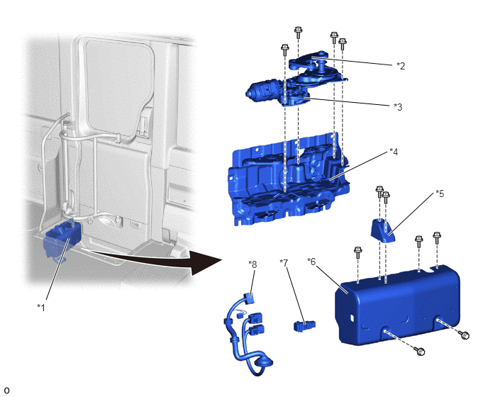
| *1 | Automatic Door Unit (Automatic Door Regulator Motor Assembly) | *2 | Power Glide Door Arm Sub-assembly |
| *3 | Glide Door Drive Motor (Power Glide Door Unit Assembly) | *4 | Power Glide Door Box Assembly RR |
| *5 | Cushion | *6 | Power Glide Door Box Assembly FR |
| *7 | Cancel Switch (Power Slide Door Main Switch) | *8 | Power Glide Door Harness Sub-assembly |
Jam Protection Mechanism
A pulse sensor (Hall IC) is integrated with the power glide door unit assembly and detects motor rotation.
The automatic door ECU reverses and stops the operation of the door if it detects a jam during automatic operation.
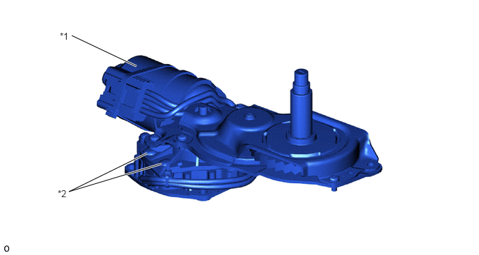
| *1 | Power Glide Door Unit Assembly | *2 | Pulse Sensor (Hall IC) |
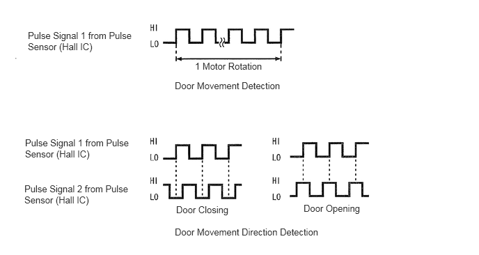
The automatic door ECU detects the amount of door movement by counting the 4-period pulse signal 1 output every 32 motor rotations by the pulse sensor (Hall IC). In addition, varying HI and LO periods of the pulse signal 2 are detected depending on the rotational direction of the motor output by the pulse sensor (Hall IC). This allows the movement direction of the door to be detected, and by storing these values the current position of the door can be recognized. The automatic door ECU controls the jam protection function based on position information obtained from these 2 pulse signals.
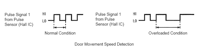
At the same time, the automatic door ECU detects changes in the movement speed of the door by detecting changes in the rotational speed of the motor from the interval of pulse signal 1 output by the pulse sensor (Hall IC). As a result, it recognizes the load on the door and performs control such as the jam protection function and stopping when there is an excessive load.