DOOR / HATCH AUTOMATIC DOOR SYSTEM(for Glide Type) DETAILS AUTO CENTER DOOR REMOTE CONTROL
CONSTRUCTION
The glide door lock remote control assembly is connected with wires and link rods to the glide door outside handle assembly, glide door inside handle, door control motor assembly, front/rear glide door lock assembly and glide door open lock assembly.
When the automatic door ECU detects a signal from the door control switch, the door control motor assembly operates, and then the front/rear glide door lock assembly and glide door open lock assembly locks are released over the wire or link rod. As a result, the glide door can move.
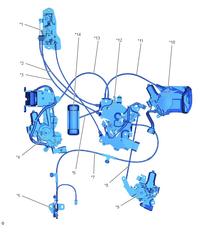
| *1 | Glide Door Inside Handle | *2 | Glide Door Lock Inside Open Cable (Open) |
| *3 | Glide Door Lock Inside Open Cable (Close) | *4 | Glide Door Lock Assembly FR |
| *5 | Glide Door Open Lock Assembly | *6 | Rear Door Open Control Link |
| *7 | Slide Door Open Cable | *8 | Door Lock Open Rod |
| *9 | Door Control Motor Assembly | *10 | Glide Door Lock Assembly RR |
| *11 | Slide Door Closer Open Cable Assembly (Rear) | *12 | Glide Door Lock Remote Control Assembly |
| *13 | Slide Door Closer Open Cable Assembly (Front) | *14 | Glide Door Outside Handle Assembly |
The glide door lock remote control assembly contains 2 types of switches to detect handle operations by a passenger from inside or outside the vehicle.
During Door Handle Opening Operation
When the inside handle (*1 in illustration) is operated in the door opening direction, the slide door lock control lever sub-assembly (*3 in illustration) is pulled through the glide door lock inside open cable (*2 in illustration) and rotated, and then the handle switch (*4 in illustration) turns on.
When the outside handle (*5 in illustration) is operated in the door opening direction, the No. 3 slide door lock control lever (*6 in illustration) and slide door lock control lever sub-assembly (*3 in illustration) are pulled through the rear door open control link (*7 in illustration) and rotated, and then the handle switch (*4 in illustration) turns on.
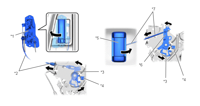
| *1 | Glide Door Inside Handle | *2 | Glide Door Lock Inside Open Cable (Open) |
| *3 | Slide Door Lock Control Lever Sub-assembly | *4 | Handle Switch (Open) |
| *5 | Glide Door Outside Handle Assembly | *6 | NO. 3 Slide Door Lock Control Lever |
| *7 | Rear Door Open Control Link | - | - |
During Door Handle Closing Operation
When the inside handle (*1 in illustration) is operated in the door closing direction, the No. 5 slide door lock control lever (*3 in illustration) is pulled through the glide door lock inside open cable (*2 in illustration) and rotated, and then the handle switch (*4 in illustration) turns on.
When the outside handle (*5 in illustration) is operated in the door closing direction, the No. 3 slide door lock control lever (*7 in illustration) and No. 5 slide door lock control lever (*3 in illustration) are pulled through the rear door open control link (*6 in illustration) and rotated, and then the handle switch (*4 in illustration) turns on.
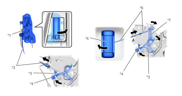
| *1 | Glide Door Inside Handle | *2 | Glide Door Lock Inside Open Cable (Close) |
| *3 | NO. 5 Slide Door Lock Control Lever | *4 | Handle Switch (Close) |
| *5 | Glide Door Outside Handle Assembly | *6 | Rear Door Open Control Link |
| *7 | NO. 3 Slide Door Lock Control Lever | - | - |
OPERATION
Opening Operation by Door Control Switch (Front/Rear Glide Door Lock Assembly Lock Released)
When an operation signal is input from the door control switch to the automatic door ECU, the automatic door ECU operates the door control motor assembly (*1 in illustration) and rotates the cam in the direction of the arrow (*a in illustration).
The door control motor assembly (*1 in illustration) transmits power over the door lock open rod (*2 in illustration) in order to the No. 6 slide door lock control lever (*3 in illustration), slide door lock control lever sub-assembly (*4 in illustration), slide door remote control pin (*5 in illustration) and No. 2 slide door lock control lever (*6 in illustration).
The No. 2 slide door lock control lever (*6 in illustration) rotates in the direction of the arrow (*b in illustration), pulling the 2 slide door closer open cable assemblies (*7 in illustration) in the direction of the arrow (*c in illustration). As a result, the latch and pawl detach, releasing the locks of the front (*8 in illustration) and rear (*9 in illustration) glide door lock assemblies.
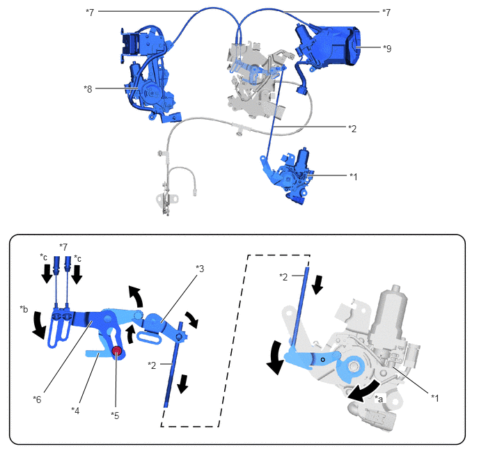
| *1 | Door Control Motor Assembly | *2 | Door Lock Open Rod |
| *3 | NO. 6 Slide Door Lock Control Lever | *4 | Slide Door Lock Control Lever Sub-assembly |
| *5 | Glide Door Lock Remote Control Pin | *6 | NO. 2 Slide Door Lock Control Lever |
| *7 | Glide Door Lock Inside Open Cable | *8 | Glide Door Lock Assembly FR |
| *9 | Glide Door Lock Assembly RR | - | - |
Closing Operation by Door Control Switch (Glide Door Open Lock Assembly Lock Released)
When an operation signal is input from the door control switch to the automatic door ECU, the automatic door ECU operates the door control motor assembly (*1 in illustration) and rotates the cam in the direction of the arrow (*a in illustration).
The door control motor assembly (*1 in illustration) transmits power over the door lock open rod (*2 in illustration) in order to the No. 6 slide door lock control lever (*3 in illustration), door lock remote control link (*4 in illustration) and No. 5 slide door lock control lever (*5 in illustration).
The No. 5 slide door lock control lever (*5 in illustration) rotates in the direction of the arrow (*b in illustration), pulling the slide door open cable (*6 in illustration) in the direction of the arrow (*c in illustration). As a result, the latch and pawl detach, releasing the lock of the glide door open lock assembly (*7 in illustration).
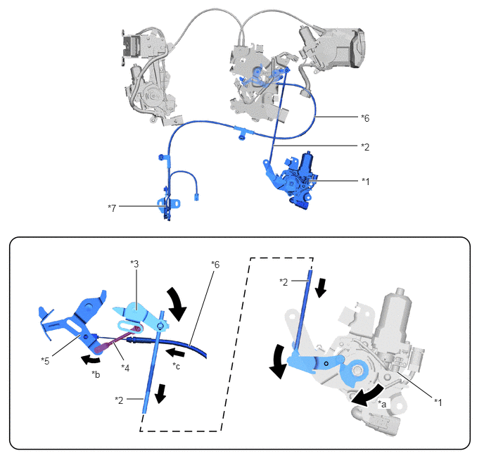
| *1 | Door Control Motor Assembly | *2 | Door Lock Open Rod |
| *3 | NO. 6 Slide Door Lock Control Lever | *4 | Door Lock Remote Control Link |
| *5 | NO. 5 Slide Door Lock Control Lever | *6 | Slide Door Open Cable |
| *7 | Glide Door Open Lock Assembly | - | - |
Opening Operation by Glide Door Outside Handle Assembly
When the glide door outside handle assembly (*1 in illustration) is operated in the opening direction (*a in illustration), the connected rear door open control link (*2 in illustration) operates in the direction of the arrow (*b in illustration).
As a result, the No. 3 slide door lock control lever (*3 in illustration) rotates in the direction of the arrow (*c in illustration), transmits power in order to the slide door lock control lever sub-assembly (*4 in illustration), slide door remote control pin (*5 in illustration) and No. 2 slide door lock control lever (*6 in illustration), and rotates in the direction of the arrow (*d in illustration).
The No. 2 slide door lock control lever (*6 in illustration) rotates in the direction of the arrow (*e in illustration), pulling the 2 slide door closer open cable assemblies (*7 in illustration) in the direction of the arrow (*f in illustration). As a result, the latch and pawl detach, releasing the locks of the front (*8 in illustration) and rear (*9 in illustration) glide door lock assemblies.
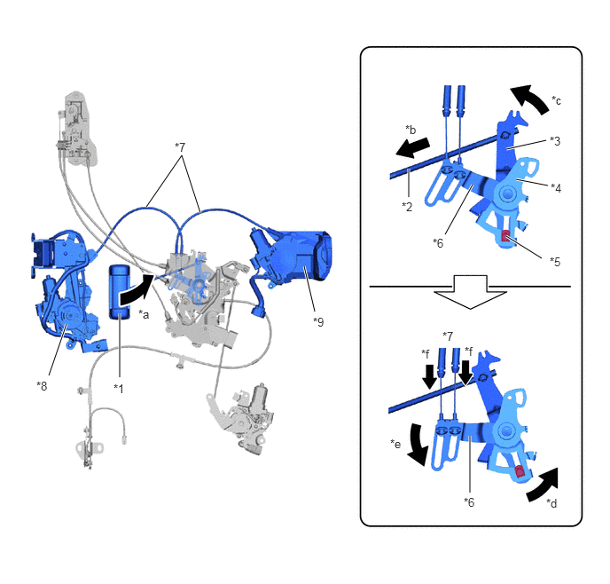
| *1 | Glide Door Outside Handle Assembly | *2 | Rear Door Open Control Link |
| *3 | NO.3 Slide Door Lock Control Lever | *4 | Slide Door Lock Control Lever Sub-assembly |
| *5 | Glide Door Lock Remote Control Pin | *6 | NO.2 Slide Door Lock Control Lever |
| *7 | Glide Door Lock Inside Open Cable | *8 | Glide Door Lock Assembly FR |
| *9 | Glide Door Lock Assembly RR | - | - |
Closing Operation by Glide Door Outside Handle Assembly
When the glide door outside handle assembly (*1 in illustration) is operated in the closing direction (*a in illustration), the connected rear door open control link (*2 in illustration) operates in the direction of the arrow (*b in illustration).
As a result, the No. 3 slide door lock control lever (*3 in illustration) rotates in the direction of the arrow (*c in illustration) and the No. 5 slide door lock control lever (*4 in illustration) is pushed in the direction of the arrow (*d in illustration).
The No. 5 slide door lock control lever (*4 in illustration) rotates in the direction of the arrow (*d in illustration), pulling the slide door open cable (*5 in illustration) in the direction of the arrow (*e in illustration). As a result, the latch and pawl detach, releasing the lock of the glide door open lock assembly (*6 in illustration).
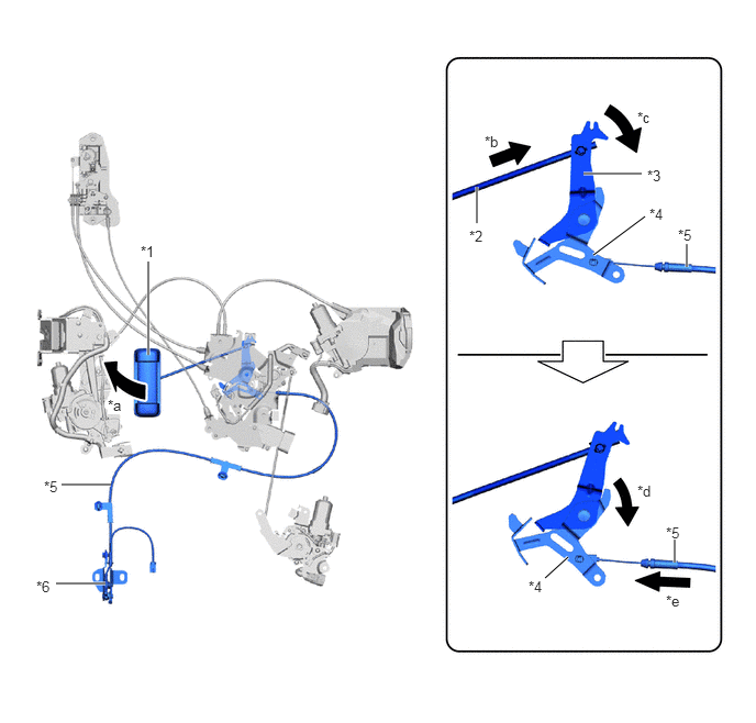
| *1 | Glide Door Outside Handle Assembly | *2 | Rear Door Open Control Link |
| *3 | NO. 3 Slide Door Lock Control Lever | *4 | NO. 5 Slide Door Lock Control Lever |
| *5 | Slide Door Open Cable | *6 | Glide Door Open Lock Assembly |
Opening Operation by Glide Door Inside Handle
When the glide door inside handle (*1 in illustration) is operated in the opening direction (*a in illustration), the connected glide door lock inside open cable (*2 in illustration) is pulled in the direction of the arrow (*b in illustration).
As a result, the slide door lock control lever sub-assembly (*3 in illustration) rotates in the direction of the arrow (*c in illustration), transmits power in order to the slide door remote control pin (*4 in illustration) and No. 2 slide door lock control lever (*5 in illustration), and rotates in the direction of the arrow (*d in illustration).
The No. 2 slide door lock control lever (*5 in illustration) rotates in the direction of the arrow (*e in illustration), pulling the two slide door closer open cable assemblies (*6 in illustration) in the direction of the arrow (*f in illustration). As a result, the latch and pawl detach, releasing the locks of the front (*7 in illustration) and rear (*8 in illustration) glide door lock assemblies.
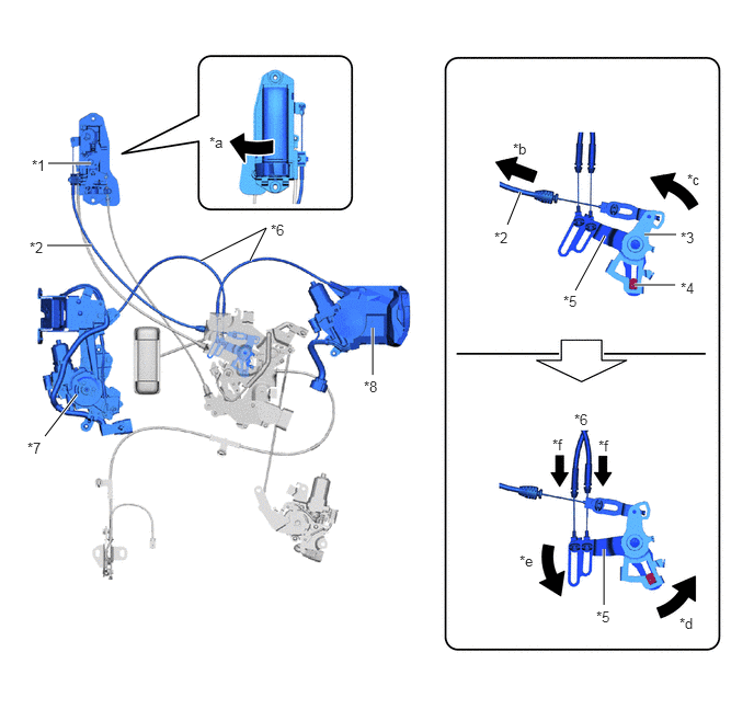
| *1 | Glide Door Inside Handle | *2 | Glide Door Lock Inside Open Cable (Open) |
| *3 | Slide Door Lock Control Lever Sub-assembly | *4 | Glide Door Lock Remote Control Pin |
| *5 | NO. 2 Slide Door Lock Control Lever | *6 | Glide Door Lock Inside Open Cable |
| *7 | Glide Door Lock Assembly FR | *8 | Glide Door Lock Assembly RR |
Closing Operation by Glide Door Inside Handle
When the glide door inside handle (*1 in illustration) is operated in the closing direction (*a in illustration), the connected glide door lock inside open cable (*2 in illustration) is pulled in the direction of the arrow (*b in illustration).
Next, the No. 5 slide door lock control lever (*3 in illustration) rotates in the direction of the arrow (*c in illustration) and the slide door open cable (*4 in illustration) is pulled in the direction of the arrow (*d in illustration). As a result, the latch and pawl detach, releasing the lock of the glide door open lock assembly (*5 in illustration).
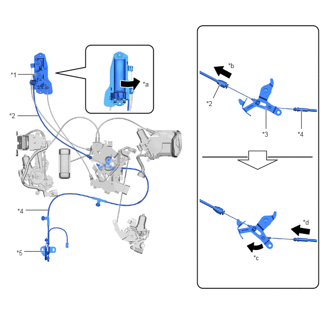
| *1 | Glide Door Inside Handle | *2 | Glide Door Lock Inside Open Cable (Close) |
| *3 | NO. 5 Slide Door Lock Control Lever | *4 | Slide Door Open Cable |
| *5 | Glide Door Open Lock Assembly | - | - |