DOOR / HATCH AUTOMATIC DOOR SYSTEM(for Glide Type) DETAILS AUTO CENTER DOOR LOCK
CONSTRUCTION
The front and rear glide door lock assemblies and the glide door open lock assembly are positioned in the glide door. Each glide door lock is connected by a cable to the glide door lock remote control assembly.
The glide door lock assembly is positioned in the front and rear of the glide door and engages with the striker on the body side when the glide door is fully closed, fixing the glide door in place.
The glide door open lock assembly engages with the striker on the glide arm side when the glide door is fully opened, fixing the glide door in place.
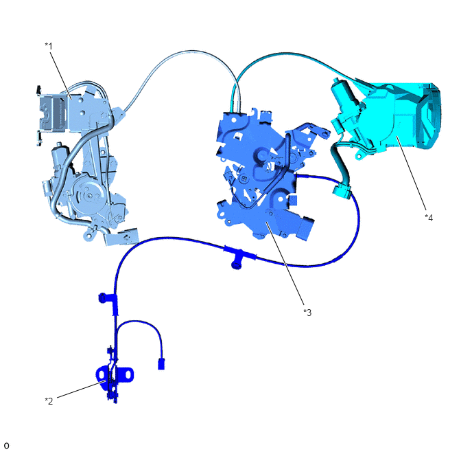
| *1 | Glide Door Lock Assembly FR | *2 | Glide Door Open Lock Assembly |
| *3 | Glide Door Lock Remote Control Assembly | *4 | Glide Door Lock Assembly RR |
Glide Door Lock Assembly
A closer function is provided for the glide door lock assembly to automatically close the glide door when the glide door is ajar.
The glide door lock assembly is positioned in the front and rear of the glide door and is composed of parts such as a closer motor, pulleys, latches, pawls, cables, levers and switches.
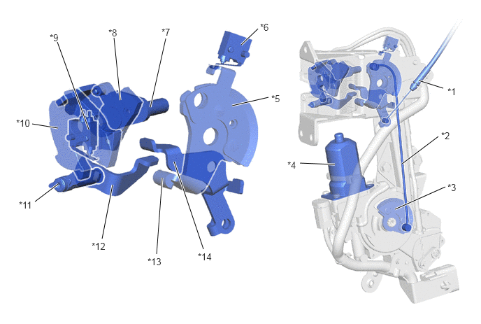
| *1 | Slide Door Closer Open Cable Assembly (Front) | *2 | Link Cable |
| *3 | Active Pulley | *4 | Closer Motor |
| *5 | Passive Pulley | *6 | Neutral Position Switch |
| *7 | Passive Lever | *8 | Latch Switch
·
Full Latch Switch ·
Half Latch Switch |
| *9 | Pawl Switch | *10 | Latch |
| *11 | Pawl | *12 | Lift Lever |
| *13 | Active Lever | *14 | Open Lever |
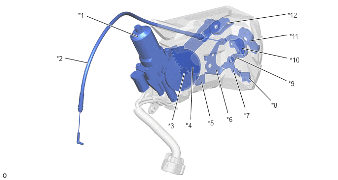
| *1 | Closer Motor | *2 | Slide Door Closer Open Cable Assembly (Rear) |
| *3 | Pinion Gear | *4 | Active Lever |
| *5 | Neutral Position Switch | *6 | Open Lever |
| *7 | Release Lever | *8 | Pawl Switch |
| *9 | Pawl | *10 | Latch Switch
·
Full Latch Switch ·
Half Latch Switch |
| *11 | Latch | *12 | Passive Lever |
Neutral Position Switch
The original position switch detects the closer motor operation position.
Neutral Position Switch (Glide Door Lock Assembly FR)
| Switch Status | Closer Motor Position |
|---|---|
| ON | Closer motor not in original position (example: closer function operating) |
| OFF | loser motor in original position (example: closer function operation completed) |
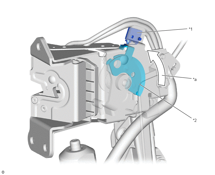
| *1 | Neutral Position Switch | *2 | Passive Pulley |
| *a | Return Direction to Original Position after Close Operation | - | - |
Neutral Position Switch (Glide Door Lock Assembly RR)
| Switch Status | Closer Motor Position |
|---|---|
| ON | Closer motor in original position (example: closer function operation completed) |
| OFF | Closer motor not in original position (example: closer function operating) |
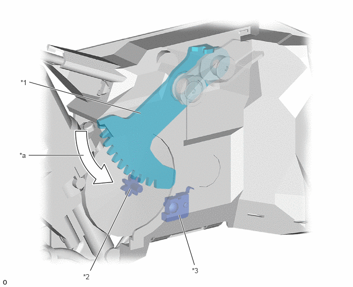
| *1 | Active Lever | *2 | Pinion Gear |
| *3 | Neutral Position Switch | - | - |
| *a | Return Direction to Original Position after Close Operation | - | - |
Latch Switch, Pawl Switch
The latch switch is composed of a full latch switch and half latch switch, and detects the latch position.
The pawl switch detects that the latch is engaged.
| Switch | Switch Status | Latch Position |
|---|---|---|
| Full Latch Switch | ON | Open side from full latch position |
| OFF | Close side from full latch position | |
| Half Latch Switch | ON | Open side from half latch position |
| OFF | Closed side from half latch position, or full latch position |
| Switch status | Door status |
|---|---|
| ON | Pawl and latch not engaged |
| OFF | Pawl and latch engaged |
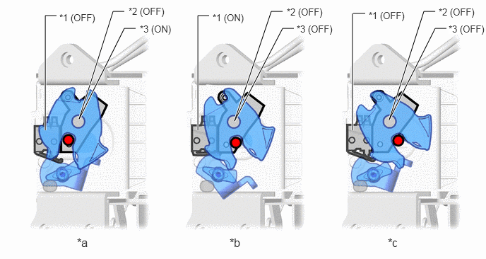
| *1 | Pawl Switch | *2 | Half Latch Switch |
| *3 | Full Latch Switch | - | - |
| *a | Half Latch | *b | Full Latch (Closer Operating in Normal Rotation) |
| *c | Full Latch (Closer Operation in Normal Rotation Completed) or Over Latch | - | - |
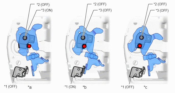
| *1 | Pawl Switch | *2 | Half Latch Switch |
| *3 | Full Latch Switch | - | - |
| *a | Half Latch | *b | Full Latch (Closer Operating in Normal Rotation) |
| *c | Full Latch (Closer Operation in Normal Rotation Completed) or Over Latch | - | - |
Glide Door Open Lock Assembly
The glide door open lock assembly is positioned in the lower center of the glide door, and engages with the striker on the glide arm side when the glide door is fully opened, fixing the glide door in place.
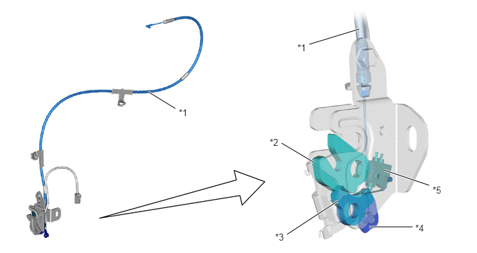
| *1 | Slide Door Open Cable Assembly | *2 | Latch |
| *3 | Pawl | *4 | Glide Door Open Lock Release Lever |
| *5 | Pawl Switch | - | - |
Pawl Switch
The pawl switch detects that the glide door is fully closed according to the pawl position.
| Switch Status | Door Status |
|---|---|
| ON | Glide door fully open |
| OFF | Glide door not fully open |
OPERATION
Close Operation (Glide Door Lock Assembly FR)
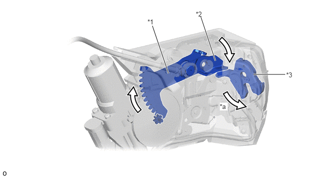
The closer motor begins rotating due to a signal from the automatic door ECU and rotates the active pulley (*1 in illustration) in the direction of the arrow (*a in illustration). The rotation of the active pulley (*1 in illustration) is transmitted over the link cable (*2 in illustration) to the passive pulley (*3 in illustration), and the passive pulley (*3 in illustration) rotates in the direction of the arrow (*b in illustration). As a result, the active lever (*4 in illustration) rotates in the direction of the arrow (*c in illustration).
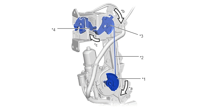
| *1 | Active Pulley | *2 | Link Cable |
| *3 | Passive Pulley | *4 | Active Lever |
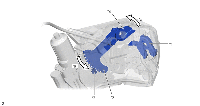
The closer motor continues to rotate, causing the active lever (*1 in illustration) to rotate the latch in the direction of the arrow (*a in illustration) over the passive lever (*2 in illustration).
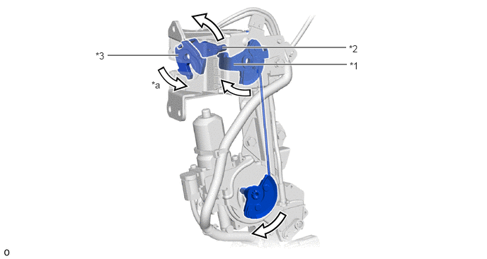
| *1 | Active Lever | *2 | Passive Lever |
After the automatic door ECU detects that the latch (*1 in illustration) is in the full lock position according to the signal from the pawl switch, the automatic door ECU rotates the closer motor in reverse, and then rotates the active pulley (*2 in illustration) in the direction of the arrow (*a in illustration). Next, the passive pulley (*3 in illustration) rotates in the direction of the arrow (*b in illustration) to return to the initial position due to the reverse rotation of the closer motor and the spring. The passive pulley (*3 in illustration) makes contact with the original position switch. When the automatic door ECU detects that it has returned to the initial position, it stops the operation of the closer motor. As a result, the closer motor operation is completed.
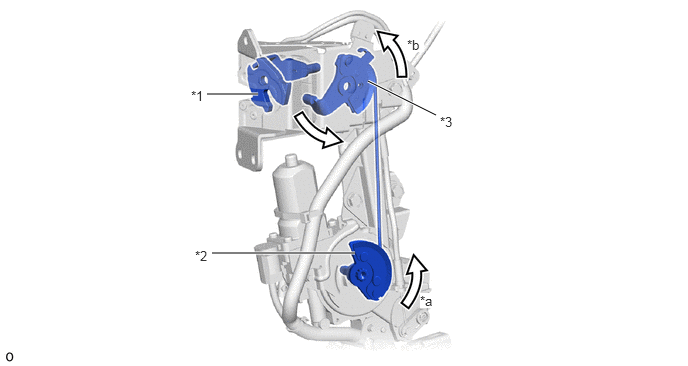
| *1 | Latch | *2 | Active Pulley |
| *3 | Passive Pulley | - | - |
Close Operation (Glide Door Lock Assembly RR)
The closer motor rotates due to the signal from the automatic door ECU, and the active lever (*2 in illustration) rotates in the direction of the arrow (*a in illustration) due to the pinion gear (*1 in illustration). When the active lever rotates, the passive lever (*3 in illustration) connected to the active lever (*2 in illustration) rotates in the direction of the arrow (*b in illustration) and pushes the latch (*4 in illustration).
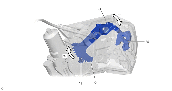
| *1 | Pinion Gear | *2 | Active Lever |
| *3 | Passive Lever | *4 | Latch |
It continues to rotate, and the active lever (*1 in illustration) rotates the latch (*3 in illustration) over the passive lever (*2 in illustration) in the direction of the arrow (*a in illustration) up to the full lock position.
| *1 | Active Lever | *2 | Passive Lever |
| *3 | Latch | - | - |
After the automatic door ECU detects that the latch (*1 in illustration) is in the full lock position according to the signal from the pawl switch, the automatic door ECU rotates the closer motor in reverse. The active lever (*3 in illustration) and passive lever (*4 in illustration) rotate in the same reverse direction (*a in illustration) in effect until now due to the pinion gear (*2 in illustration). When the active lever (*3 in illustration) makes contact with the original position switch, the automatic door ECU stops the operation of the closer motor. As a result, the closer motor operation is completed.
| *1 | Latch | *2 | Pinion Gear |
| *3 | Active Lever | *4 | Passive Lever |
Release Operation (Glide Door Lock Assembly FR)
The open cable (*1 in illustration) connected from the glide door lock remote control assembly is pulled in the direction of the arrow (*a in illustration) due to the operation of the door control switch or the operation of the door handle from inside or outside the vehicle. Next, the open lever (*2 in illustration) connected to the open cable (*1 in illustration) rotates in the direction of the arrow (*b in illustration). The open lever (*2 in illustration) rotates while pushing the lift lever (*4 in illustration) connected to the pawl (*3 in illustration), so the pawl (*3 in illustration) and latch (*5 in illustration) detach. As a result, the release operation is completed.
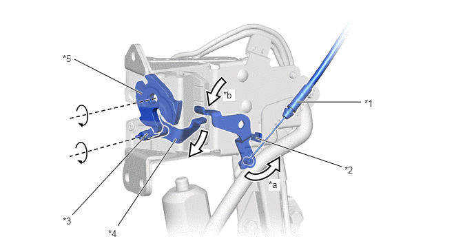
| *1 | Open Cable (Slide Door Closer Open Cable Assembly) | *2 | Open Lever |
| *3 | Pawl | *4 | Lift Lever |
| *5 | Latch | - | - |
Release Operation (Glide Door Lock Assembly RR)
The open cable (*1 in illustration) connected from the glide door lock remote control assembly is pulled in the direction of the arrow (*a in illustration) due to the operation of the door control switch or the operation of the door handle from inside or outside the vehicle. Next, the open lever (*2 in illustration) connected to the open cable (*1 in illustration) rotates in the direction of the arrow (*b in illustration). The open lever (*2 in illustration) pushes the release lever (*3 in illustration) and rotates it in the direction of the arrow (*c in illustration), so the pawl (*4 in illustration) and latch (*5 in illustration) detach. As a result, the release operation is completed.
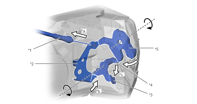
| *1 | Open Cable (Slide Door Closer Open Cable Assembly) | *2 | Open Lever |
| *3 | Release Lever | *4 | Pawl |
| *5 | Latch | - | - |
Open Lock Operation (Glide Door Open Lock Assembly)
When the glide door moves in the opening direction, the door lock striker (*1 in illustration) on the glide arm side approaches the glide door open lock assembly. (*A in illustration)
When the door lock striker (*1 in illustration) advances while pushing the latch (*2 in illustration), the pawl (*3 in illustration) rotates in the direction of the arrow (*a in illustration) when the glide door is in the fully open position and engages with the latch (*2 in illustration). As a result, the latch (*2 in illustration) can no longer rotate in the release direction, and the glide door is retained at the fully open position. (*B in illustration)
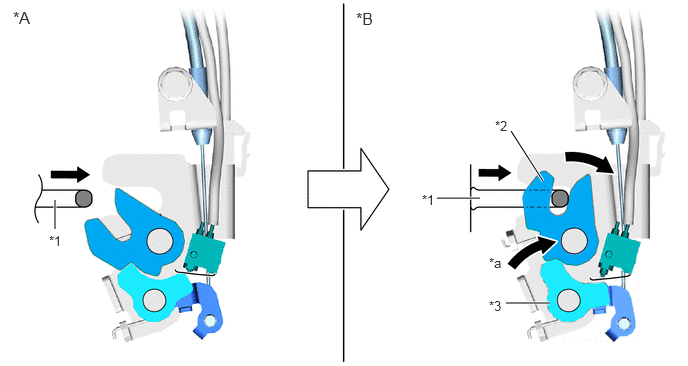
| *1 | Door Lock Striker | *2 | Latch |
| *3 | Pawl | - | - |
Lock Release Operation (Glide Door Open Lock Assembly)
The glide door open lock release lever (*2 in illustration) is pulled in the direction of the arrow (*a in illustration) over the open cable (*1 in illustration) due to the glide door lock remote control assembly. As a result, the pawl (*3 in illustration) rotates in the direction of the arrow (*b in illustration). (*A in illustration)
The pawl (*3 in illustration) rotates and detaches from the latch (*4 in illustration), allowing the latch (*4 in illustration) to rotate in the lock release direction (*c in illustration). As a result, the lock release operation is completed. The door lock striker (*5 in illustration) is released in the direction of the arrow (*d in illustration) and the glide door can now move in the closing direction. (*B in illustration)
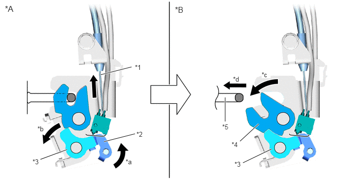
| *1 | Open Cable (Slide Door Open Cable Assembly) | *2 | Pawl |
| *3 | Latch | *4 | Door Lock Striker |