Home › Brake › BRAKE CONTROL / DYNAMIC CONTROL SYSTEMS › BRAKE CONTROL SYSTEM (w/ ABS) › from 2021.01
NM2850E _54 Brake _073399 BRAKE CONTROL / DYNAMIC CONTROL SYSTEMS _0357377 BRAKE CONTROL SYSTEM(w/ ABS) DE DETAILS F

BRAKE CONTROL / DYNAMIC CONTROL SYSTEMS  BRAKE CONTROL SYSTEM(w/ ABS)  DETAILS  BRAKE ACTUATOR  


CONSTRUCTION


a.

A brake actuator assembly integrated with a skid control computer was employed for vehicles with an ABS that uses CAN communication. The brake actuator assembly has a small size and light weight while still having sufficient ejection performance and guarantees excellent safety and running performance even for heavy vehicles.


b.

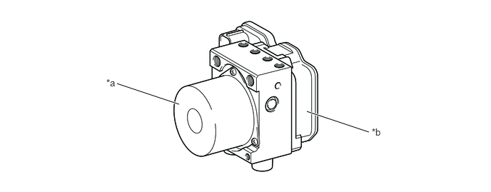
The brake actuator assembly consists of the actuator, skid control ECU, solenoid relay, pump motor, and master cylinder pressure sensor.
X141239C01
1.708,1.219 2.615,1.521 true 4.479,1.625 5.385,1.927 true 1.552,1.125 1.865,1.323 0.313,0.198 10 false *a 5.427,1.844 5.74,2.042 0.313,0.198 10 false *b
*a Actuator Portion *b Skid Control ECU


c.

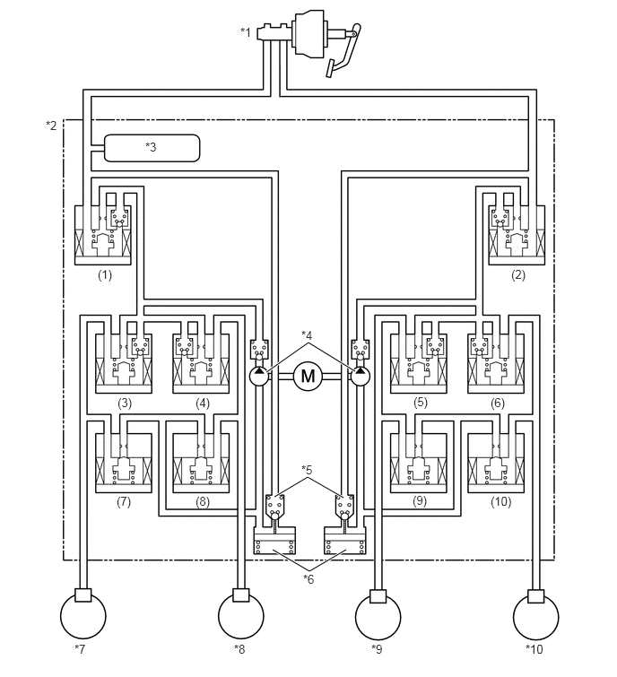
The actuator portion consists of 10 solenoid valves, 2 pressure regulator valves, 2 pump, 2 reservoirs, and master cylinder pressure sensor.


d.

The 10 solenoid valves consist of 2 master cylinder cut solenoid valves [(1), (2)], 4 pressure holding solenoid valves [(3), (4), (5), (6)], and 4 pressure reduction solenoid valves [(7), (8), (9), (10)].
Hydraulic Circuit
X141240C01
3.094,4.323 3.583,3.979 3.583,3.979 4.125,4.313 true 3.188,5.771 3.573,5.542 3.573,5.542 3.99,5.781 true 3.167,6.385 3.594,6.635 3.594,6.635 4.021,6.385 true 2.792,0.292 3.135,0.542 0.344,0.25 10 false *1 0.531,1.375 0.875,1.625 0.344,0.25 10 false *2 1.688,1.625 2.031,1.875 0.344,0.25 10 false *3 3.5,3.813 3.844,4.063 0.344,0.25 10 false *4 3.5,5.375 3.844,5.625 0.344,0.25 10 false *5 3.521,6.646 3.865,6.896 0.344,0.25 10 false *6 0.865,7.458 1.208,7.708 0.344,0.25 10 false *7 2.719,7.458 3.063,7.708 0.344,0.25 10 false *8 4.313,7.458 4.667,7.708 0.354,0.25 10 false *9 6.104,7.458 6.458,7.708 0.354,0.25 10 false *10 1.135,3.104 1.479,3.354 0.344,0.25 10 false (1) 5.938,3.104 6.281,3.354 0.344,0.25 10 false (2) 1.365,4.594 1.708,4.844 0.344,0.25 10 false (3) 4.802,4.583 5.146,4.833 0.344,0.25 10 false (5) 2.271,4.594 2.615,4.844 0.344,0.25 10 false (4) 5.698,4.594 6.042,4.844 0.344,0.25 10 false (6) 1.354,5.74 1.698,5.99 0.344,0.25 10 false (7) 2.271,5.74 2.615,5.99 0.344,0.25 10 false (8) 4.792,5.729 5.135,5.979 0.344,0.25 10 false (9) 5.698,5.74 6.042,5.99 0.344,0.25 10 false (10)
*1 Brake Master Cylinder Sub-assembly *2 Brake Actuator Assembly
*3 Master Cylinder Pressure Sensor *4 Pump
*5 Pressure Regulator Valves *6 Reservoirs
*7 Rear Left Wheel Cylinder *8 Rear Right Wheel Cylinder
*9 Front Left Wheel Cylinder *10 Front Right Wheel Cylinder


OPERATION


a.

ABS with EBD Operation

·

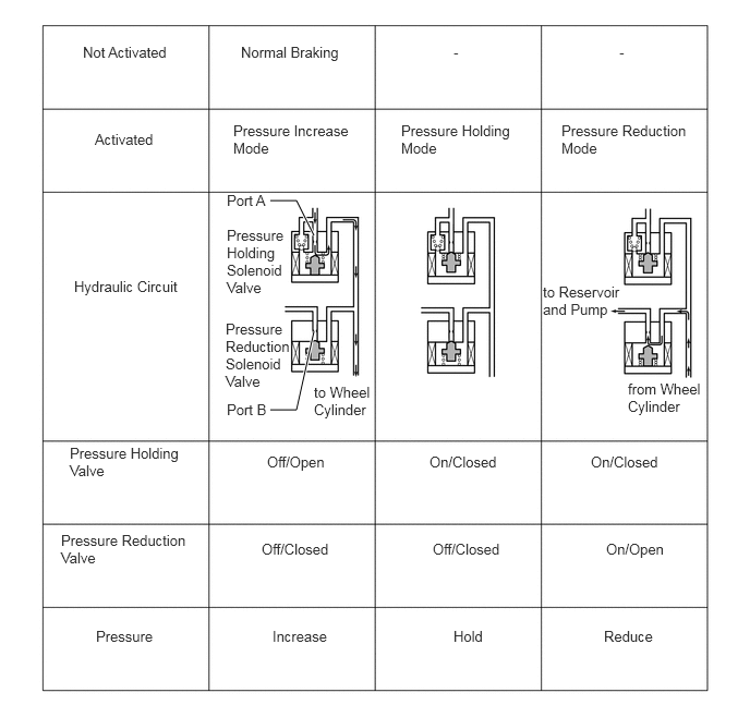
Based on the signals received from the 4 wheel speed sensors and yaw rate and deceleration sensor, the skid control ECU calculates the wheel rotation speed and deceleration for each wheel, in order to check for a wheel slippage condition. According to the slippage condition, the ECU controls the pressure holding solenoid valves and pressure reduction solenoid valves in order to adjust the fluid pressure of the brakes for each of the wheels in the following 3 modes: pressure reduction, pressure holding, and pressure increase modes.
X141247E01
2.583,1.917 2.833,1.917 2.833,1.917 3,2.25 true 3,3.167 2.833,3.917 2.833,3.917 2.583,3.917 true 0.792,0.417 1.75,0.802 0.958,0.385 10 false Not Activated 2.302,0.417 3.333,0.802 1.031,0.385 10 false Normal Braking 4.333,0.417 4.667,0.833 0.333,0.417 10 false - 5.917,0.417 6.25,0.833 0.333,0.417 10 false - 0.906,1.25 1.865,1.635 0.958,0.385 10 false Activated 2.229,1.167 3.354,1.833 1.125,0.667 10 false Pressure Increase Mode 3.833,1.167 4.917,1.833 1.083,0.667 10 false Pressure Holding Mode 5.365,1.167 6.615,1.833 1.25,0.667 10 false Pressure Reduction Mode 0.708,2.656 1.792,3.073 1.083,0.417 10 false Hydraulic Circuit 2.167,2.167 2.75,3.5 0.583,1.333 10 false Pressure Holding Solenoid Valve 2.156,3.063 2.823,4.396 0.667,1.333 10 false Pressure Reduction Solenoid Valve 3,3.667 3.667,4.333 0.667,0.667 10 false to Wheel Cylinder 2.167,1.833 2.667,2.25 0.5,0.417 10 false Port A 2.167,3.833 2.667,4.25 0.5,0.417 10 false Port B 5.188,2.708 5.938,3.375 0.75,0.667 10 false to Reservoir and Pump 6,3.635 6.75,4.302 0.75,0.667 10 false from Wheel Cylinder 0.667,4.25 1.75,4.917 1.083,0.667 10 false Pressure Holding Valve 0.583,5.083 1.833,5.75 1.25,0.667 10 false Pressure Reduction Valve 0.917,6 1.583,6.5 0.667,0.5 10 false Pressure 2.552,4.333 3.219,4.833 0.667,0.5 10 false Off/Open 4.104,4.333 4.854,4.833 0.75,0.5 10 false On/Closed 5.646,4.333 6.396,4.833 0.75,0.5 10 false On/Closed 2.5,5.167 3.25,5.667 0.75,0.5 10 false Off/Closed 4.135,5.167 4.885,5.667 0.75,0.5 10 false Off/Closed 5.792,5.167 6.542,5.667 0.75,0.5 10 false On/Open 2.604,6 3.354,6.5 0.75,0.5 10 false Increase 4.333,6 5.083,6.5 0.75,0.5 10 false Hold 5.771,6 6.521,6.5 0.75,0.5 10 false Reduce


b.

Power Assist Brake (PAB) Operation

·

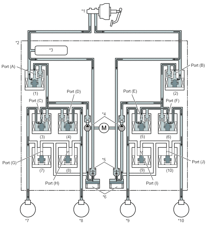
In certain situations when the vacuum pressure of the vacuum booster calculated using the vacuum sensor and master cylinder pressure sensor is low, the skid control ECU may provide brake assist. Or in the event of a brake booster failure, based on the brake pedal load sensing switch and master cylinder pressure sensor signal, the skid control ECU may provide brake assist.

·

If the skid control ECU judges the need for additional brake assist, pressure is generated by the pump in the brake actuator and directed to the wheel cylinder to apply a large amount of fluid pressure.
Power Assist Brake (PAB) Circuit
X141241C01
3.094,4.323 3.583,3.979 3.583,3.979 4.125,4.313 true 3.188,5.771 3.573,5.542 3.573,5.542 3.99,5.781 true 3.167,6.385 3.594,6.635 3.594,6.635 4.021,6.385 true 1.177,2.521 0.573,2.281 true 6.521,2.219 6.01,2.51 true 1.417,4 1.26,3.521 true 2.323,4.01 2.542,3.229 true 4.844,4.01 4.521,3.229 true 5.76,4.01 5.875,3.531 true 1.427,5.177 0.583,5.552 true 2.323,5.177 1.833,6.156 true 4.844,5.198 5.25,6.156 true 5.75,5.167 6.542,5.5 true 2.792,0.292 3.135,0.542 0.344,0.25 10 false *1 0.531,1.375 0.875,1.625 0.344,0.25 10 false *2 1.688,1.625 2.031,1.875 0.344,0.25 10 false *3 3.5,3.813 3.844,4.063 0.344,0.25 10 false *4 3.5,5.375 3.844,5.625 0.344,0.25 10 false *5 3.521,6.646 3.865,6.896 0.344,0.25 10 false *6 0.865,7.458 1.208,7.708 0.344,0.25 10 false *7 2.719,7.458 3.063,7.708 0.344,0.25 10 false *8 4.313,7.458 4.667,7.708 0.354,0.25 10 false *9 6.104,7.458 6.458,7.708 0.354,0.25 10 false *10 1.135,3.104 1.479,3.354 0.344,0.25 10 false (1) 5.938,3.104 6.281,3.354 0.344,0.25 10 false (2) 1.365,4.594 1.708,4.844 0.344,0.25 10 false (3) 4.802,4.583 5.146,4.833 0.344,0.25 10 false (5) 2.271,4.594 2.615,4.844 0.344,0.25 10 false (4) 5.698,4.594 6.042,4.844 0.344,0.25 10 false (6) 1.354,5.74 1.698,5.99 0.344,0.25 10 false (7) 2.271,5.74 2.615,5.99 0.344,0.25 10 false (8) 4.792,5.729 5.135,5.979 0.344,0.25 10 false (9) 5.698,5.74 6.042,5.99 0.344,0.25 10 false (10) 0.052,2.188 0.646,2.573 0.594,0.385 10 false Port (A) 6.552,2.146 7.073,2.542 0.521,0.396 10 false Port (B) 0.99,3.354 1.51,3.75 0.521,0.396 10 false Port (C) 2.292,3.042 2.813,3.438 0.521,0.396 10 false Port (D) 4.229,3.031 4.75,3.427 0.521,0.396 10 false Port (E) 5.688,3.354 6.208,3.75 0.521,0.396 10 false Port (F) 0.083,5.479 0.604,5.875 0.521,0.396 10 false Port (G) 1.552,6.177 2.073,6.573 0.521,0.396 10 false Port (H) 5.01,6.177 5.531,6.573 0.521,0.396 10 false Port (I) 6.583,5.448 7.104,5.844 0.521,0.396 10 false Port (J)
*1 Brake Master Cylinder Sub-assembly *2 Brake Actuator Assembly
*3 Master Cylinder Pressure Sensor *4 Pump
*5 Pressure Regulator Valves *6 Reservoirs
*7 Rear Left Wheel Cylinder *8 Rear Right Wheel Cylinder
*9 Front Left Wheel Cylinder *10 Front Right Wheel Cylinder


Power Assist Brake (PAB) Control
Item Power Assist Brake (PAB) Not Activated Power Assist Brake (PAB) Activated

*: The solenoid valves control the hydraulic pressure by adjusting continually between "open" and "closed" according to the operating conditions.

(1), (2) Master Cylinder Cut Solenoid Valve OFF/Open ON*
Port: (A), (B)
(3), (4), (5), (6) Pressure Holding Solenoid Valve OFF/Open OFF/Open
Port: (C), (D), (E), (F)
(7), (8), (9), (10) Pressure Reduction Solenoid Valve OFF/Closed OFF/Closed
Port: (G), (H), (I), (J)


c.

Brake Assist Operation

·

In the event of emergency braking, the skid control ECU determines the driver's intention based on the speed of the pressure increase in the master cylinder determined by the master cylinder pressure sensor signal. If the skid control ECU determines the need for additional brake assist, pressure is generated by the pump in the brake actuator assembly and directed to the wheel cylinder to apply a large amount of fluid pressure.

Brake Assist Circuit
X141241C01
3.094,4.323 3.583,3.979 3.583,3.979 4.125,4.313 true 3.188,5.771 3.573,5.542 3.573,5.542 3.99,5.781 true 3.167,6.385 3.594,6.635 3.594,6.635 4.021,6.385 true 1.177,2.521 0.573,2.281 true 6.521,2.219 6.01,2.51 true 1.417,4 1.26,3.521 true 2.323,4.01 2.542,3.229 true 4.844,4.01 4.521,3.229 true 5.76,4.01 5.875,3.531 true 1.427,5.177 0.583,5.552 true 2.323,5.177 1.833,6.156 true 4.844,5.198 5.25,6.156 true 5.75,5.167 6.542,5.5 true 2.792,0.292 3.135,0.542 0.344,0.25 10 false *1 0.531,1.375 0.875,1.625 0.344,0.25 10 false *2 1.688,1.625 2.031,1.875 0.344,0.25 10 false *3 3.5,3.813 3.844,4.063 0.344,0.25 10 false *4 3.5,5.375 3.844,5.625 0.344,0.25 10 false *5 3.521,6.646 3.865,6.896 0.344,0.25 10 false *6 0.865,7.458 1.208,7.708 0.344,0.25 10 false *7 2.719,7.458 3.063,7.708 0.344,0.25 10 false *8 4.313,7.458 4.667,7.708 0.354,0.25 10 false *9 6.104,7.458 6.458,7.708 0.354,0.25 10 false *10 1.135,3.104 1.479,3.354 0.344,0.25 10 false (1) 5.938,3.104 6.281,3.354 0.344,0.25 10 false (2) 1.365,4.594 1.708,4.844 0.344,0.25 10 false (3) 4.802,4.583 5.146,4.833 0.344,0.25 10 false (5) 2.271,4.594 2.615,4.844 0.344,0.25 10 false (4) 5.698,4.594 6.042,4.844 0.344,0.25 10 false (6) 1.354,5.74 1.698,5.99 0.344,0.25 10 false (7) 2.271,5.74 2.615,5.99 0.344,0.25 10 false (8) 4.792,5.729 5.135,5.979 0.344,0.25 10 false (9) 5.698,5.74 6.042,5.99 0.344,0.25 10 false (10) 0.052,2.188 0.646,2.573 0.594,0.385 10 false Port (A) 6.552,2.146 7.073,2.542 0.521,0.396 10 false Port (B) 0.99,3.354 1.51,3.75 0.521,0.396 10 false Port (C) 2.292,3.042 2.813,3.438 0.521,0.396 10 false Port (D) 4.229,3.031 4.75,3.427 0.521,0.396 10 false Port (E) 5.688,3.354 6.208,3.75 0.521,0.396 10 false Port (F) 0.083,5.479 0.604,5.875 0.521,0.396 10 false Port (G) 1.552,6.177 2.073,6.573 0.521,0.396 10 false Port (H) 5.01,6.177 5.531,6.573 0.521,0.396 10 false Port (I) 6.583,5.448 7.104,5.844 0.521,0.396 10 false Port (J)
*1 Brake Master Cylinder Sub-assembly *2 Brake Actuator Assembly
*3 Master Cylinder Pressure Sensor *4 Pump
*5 Pressure Regulator Valves *6 Reservoirs
*7 Rear Left Wheel Cylinder *8 Rear Right Wheel Cylinder
*9 Front Left Wheel Cylinder *10 Front Right Wheel Cylinder


Brake Assist Control
Item Brake Assist Not Activated Brake Assist Activated

*: The solenoid valves control the hydraulic pressure by adjusting continually between "open" and "closed" according to the operating conditions.

(1), (2) Master Cylinder Cut Solenoid Valve OFF/Open ON*
Port: (A), (B)
(3), (4), (5), (6) Pressure Holding Solenoid Valve OFF/Open OFF/Open
Port: (C), (D), (E), (F)
(7), (8), (9), (10) Pressure Reduction Solenoid Valve OFF/Closed OFF/Closed
Port: (G), (H), (I), (J)


d.

Initial Check

·

After the ignition switch is turned ON (IG), and the vehicle attains an approximate speed of 6 km/h (4 mph) or more, the skid control ECU performs the initial check.

·

The functions of each solenoid valve and pump motor in the brake actuator assembly are checked in order.