EXHAUST BRAKE EXHAUST BRAKE SYSTEM CONTROL EXHAUST RETARDER CONTROL
FUNCTION OF MAIN COMPONENTS
| Component | Function |
|---|---|
|
*1: Models without brake cooperative type exhaust brake system *2: Models with manual transmission *3: Models with automatic transmission *4: Models with brake cooperative type exhaust brake system |
|
| Exhaust Retarder Solenoid | Switches between atmospheric pressure and negative pressure applied to the vacuum cylinder, opening and closing the exhaust retarder valve. |
| Exhaust Brake Switch*1 | Pulling the exhaust brake switch (incorporated in the wiper control switch) toward the driver activates the exhaust retarder and causes the indicator light in the combination meter to illuminate. |
| Clutch Switch*2 | Detects clutch engagement according to clutch pedal operation; depressing the clutch pedal turns off current to the exhaust retarder solenoid. |
| Neutral Switch*2 | Detects engagement of neutral or any other gear. |
| Neutral Start Switch*3 | Detects the shift lever position. |
| Stop Light Switch Assembly*4 | Detects the brake pedal operation condition. |
| Vehicle Speed Sensor | Built into speedometer; detect vehicle speed and send it to the engine ECU. |
| ECM | Controls the exhaust retarder solenoid. |
| Component | Function |
|---|---|
| Exhaust Retarder Solenoid | Switches between atmospheric pressure and negative pressure applied to the vacuum cylinder, opening and closing the exhaust retarder valve. |
| Exhaust Brake Switch | Pulling the exhaust brake switch (incorporated in the wiper control switch) toward the driver activates the exhaust retarder and causes the indicator light in the combination meter to illuminate. |
| Clutch Switch | Detects clutch engagement according to clutch pedal operation; depressing the clutch pedal turns off current to the exhaust retarder solenoid. |
| Neutral Switch | Detects engagement of neutral or any other gear. |
| Accelerator Pedal Switch Assembly | Detects the accelerator pedal operation condition. |
| Stop Light Control ECU | Controls the EXH cut relay based on signals form the skid control ECU. |
| Skid Control ECU | Controls the stop light control ECU. |
OPERATING CONDITION
| Objective | Operating Conditions |
|---|---|
|
*1: Models without brake cooperative type exhaust brake system *2: Models with manual transmission *3: Models with N04C-UH, N04C-VL, N04C-VQ, N04C-WA or N04C-VJ engine *4: Models with N04C-UH, N04C-WA or N04C-VJ engine |
|
| Exhaust Brake | ·
Exhaust brake switch is ON.*1 ·
Clutch is not operating.*2 ·
Accelerator pedal is not operating. ·
Vehicle speed is more than predetermined value. ·
Transmission is not in neutral. ·
ABS is not operating. |
| Long time Idling Control*3 | ·
Vehicle is stopped. ·
Engine is idling for a long time. ·
Clutch is not operating.*2 ·
Accelerator pedal is not operating. ·
Transmission is in neutral. |
| DPF Control*4 | Vehicle is stopped and the engine is idling during DPF catalytic converter cleaning mode. |
SYSTEM CONTROL
The engine braking effect is boosted by closing a valve provided in the exhaust pipe and narrowing the exhaust gas passage. The stop lights illuminate when this function operates.
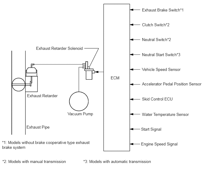
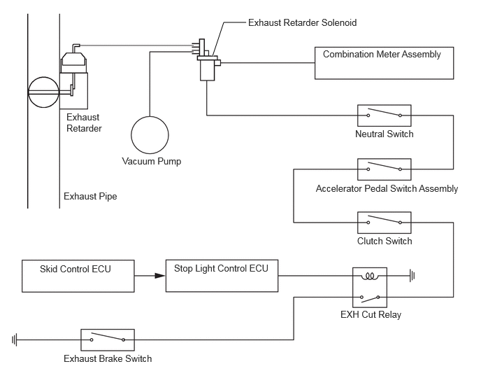
When the engine idles for a long period of time, unburned HC accumulates in the catalytic converter. This causes white smoke to be emitted when the vehicle starts off. For this reason, the system effects longtime idling control to reduce HC. This control raises the idle speed and closes the exhaust retarder valve when the engine idles for a long time.*
*: Models with N04C-UH, N04C-VL, N04C-VQ, N04C-WA or N04C-VJ engine
FAIL-SAFE
When the engine ECU detects a malfunction, it stops or controls the engine according to the data already stored in the memory. For details, refer to the Repair Manual.
DIAGNOSIS
When the engine ECU detects a malfunction, it outputs DTCs (Diagnosis Trouble Codes) and memorizes the failed section. Furthermore, the check engine warning light in the combination meter illuminates to inform the driver.
At the same time, the DTCs are stored in memory. The DTCs can be read by connecting a Global TechStream (GTS).
For details, refer to the Repair Manual.