1BZ-FPE ENGINE CONTROL ELECTRONIC CONTROLLED CARBURETOR SYSTEM P0105 Manifold Absolute Pressure / Barometric Pressure Circuit
DESCRIPTION
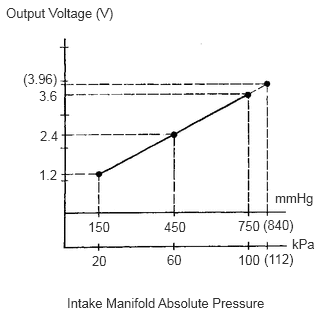
By a built-in sensor unit, the vacuum sensor detects the intake manifold pressure as a voltage. The engine ECU then determines the basic injection duration and basic ignition advance angle based on this voltage.
Since the vacuum sensor does not use the atmospheric pressure as a criterion, but senses the absolute pressure inside the intake manifold (the pressure in proportion to the preset absolute vacuum 0), it is not influenced by fluctuations in the atmospheric pressure due to high altitude and other factors. this permits it to control the air-fuel ratio at the proper level under all conditions.
| DTC No. | DTC Detecting Condition | Trouble Area |
|---|---|---|
| P0105/31 | Open or short in vacuum sensor circuit | ·
Open or short in vacuum sensor circuit ·
Vacuum sensor ·
Engine ECU |
- HINT:
-
After confirming DTC P0105, use the hand-held tester to confirm the manifold absolute pressure from "CURRENT DATA".
| Manifold Absolute Pressure (kPa) | Malfunction |
|---|---|
| Approx. 0 | ·
PIM circuit short |
| 130 or more | ·
VC circuit open or short ·
PIM circuit open ·
E2 circuit open |
WIRING DIAGRAM
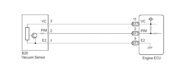
CAUTION / NOTICE / HINT
- HINT:
- ·
If DTC P0105 (Vacuum Sensor Circuit Malfunction), P0110 (Intake Air Temp. Circuit Malfunction), P0115 (Water Temp. Circuit Malfunction), P0120 (Throttle Position Sensor Circuit Malfunction) are output simultaneously, E2 (sensor ground) may be open.
·Read freeze frame data using hand-held tester. Because freeze frame records the engine conditions when the malfunction is detected, when troubleshooting it is useful for determining whether the vehicle was running or stopped, the engine warmed up or not, the air-fuel ratio lean or rich, etc. at the time of the malfunction.
PROCEDURE
PREPARATION:
Connect the hand-held tester to the DLC3.
Turn ignition switch ON and hand-held tester main switch ON.
CHECK:
Read value of manifold absolute pressure on the hand-held tester.
- OK:
Same as atmospheric pressure.
- Result:
Proceed to OK NG
OK
NG
PREPARATION:
Remove the side trim bracket.
Turn the ignition switch ON.
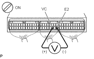
CHECK:
Measure voltage between terminals VC and E2 of engine ECU.
- OK:
Voltage: 4.5 - 5.5 V
- Result:
Proceed to OK NG
OK
NG
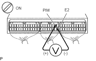
PREPARATION:
Remove the side trim bracket.
Turn the ignition switch ON.
CHECK:
Measure voltage between terminals PIM and E2 of engine ECU.
- OK:
Voltage: 3.3 - 3.9 V
- Result:
Proceed to OK NG
OK
NG
(Click here General>INTRODUCTION>HOW TO TROUBLESHOOT ECU CONTROLLED SYSTEMS>ELECTRONIC CIRCUIT INSPECTION PROCEDURE)
- Result:
Proceed to OK NG
OK
NG