Home › Engine / Hybrid System › 1BZ-FPE (ENGINE CONTROL) › ELECTRONIC CONTROLLED CARBURETOR SYSTEM › 2017.01–2021.01
RM2850E _51 Engine / Hybrid System _073136 1BZ-FPE ENGINE CONTROL _0355837 ELECTRONIC CONTROLLED CARBURETOR SYSTEM C

1BZ-FPE ENGINE CONTROL  ELECTRONIC CONTROLLED CARBURETOR SYSTEM  P0130  Oxygen Sensor Circuit (Bank 1 Sensor 1)  


DESCRIPTION

To obtain a high purification rate for the CO, HC and NOx components of the exhaust gas, a three-way catalytic converter is used, but for the most efficient use of the three-way catalytic converter, the air-fuel ratio must be precisely controlled so that it is always close to the stoichiometric air-fuel ratio.

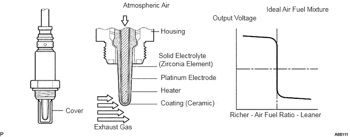
The oxygen sensor has the characteristic which its output voltage changes suddenly in the vicinity of the stoichiometric air-fuel ratio. This characteristic is used to detect the oxygen concentration in the exhaust gas and provide the engine ECU with feedback to control of the air-fuel ratio.

When the air-fuel ratio becomes LEAN, the oxygen concentration in the exhaust increases and the oxygen sensor informs the engine ECU of the LEAN condition (small electromotive force: < 0.45 V).

When the air-fuel ratio is RICHER than the stoichiometric air-fuel ratio the oxygen concentration in the exhaust gas is reduced and the oxygen sensor informs the engine ECU of the RICH condition (large electromotive force: > 0.45 V). The engine ECU judges by the electromotive force from the oxygen sensor whether the air-fuel ratio is RICH or LEAN and controls the injection time accordingly. However, if malfunction of the oxygen sensor causes output of abnormal electromotive force, the engine ECU is unable to perform accurate air-fuel ratio control. The oxygen sensors include a heater which heats the zirconia element. The heater is controlled by the engine ECU. When the intake air volume is low (the temperature of the exhaust gas is low) current flows to the heater to heat the sensor for accurate oxygen concentration detection.
A088111E52
1.292,2.26 1.073,2.26 false 3.094,0.646 3.26,0.646 false 2.521,0.021 3.792,0.25 1.271,0.229 10 false Atmospheric Air 3.292,0.552 3.938,0.75 0.646,0.198 10 false Housing 3.292,1.5 4.5,1.698 1.208,0.198 10 false Platinum Electrode 3.292,1.76 3.823,1.958 0.531,0.198 10 false Heater 3.292,2.021 4.458,2.219 1.167,0.198 10 false Coating (Ceramic) 1.927,2.51 2.792,2.708 0.865,0.198 10 false Exhaust Gas 1.344,2.177 1.771,2.375 0.427,0.198 10 false Cover 5.458,0.104 6.865,0.302 1.406,0.198 10 false Ideal Air Fuel Mixture 4.708,2.26 6.667,2.427 1.958,0.167 10 false Richer - Air Fuel Ratio - Leaner 4.354,0.281 5.313,0.479 0.958,0.198 10 false Output Voltage 3.25,1.052 4.385,1.417 1.135,0.365 10 false Solid Electrolyte (Zirconia Element)

DTC No. DTC Detection Condition Trouble Area
P0130/21
·

Voltage output of oxygen sensor remains at 0.4 V or more, or 0.55 V or less, during idling after engine is warmed up

·

Open or short in oxygen sensor circuit (2 trip detection logic)


·

Open or short in oxygen sensor circuit

·

Oxygen sensor

·

Air induction system

·

Fuel pressure

·

Injector

·

Engine ECU


HINT:
·

The oxygen sensor output voltage and the short-term fuel trim value can be read by using the hand- held tester.

·

If the voltage output of the oxygen sensor is 0 V, the oxygen sensor circuit may be open or short.


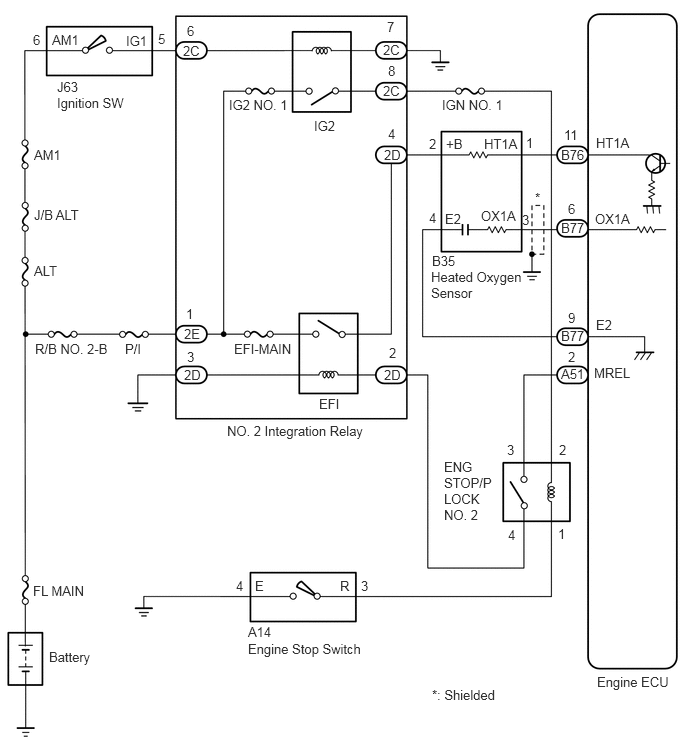
WIRING DIAGRAM
A403046E01
0.344,0.333 0.5,0.531 0.156,0.198 10 false 6 0.542,0.333 0.875,0.5 0.333,0.167 10 false AM1 1.313,0.344 1.604,0.521 0.292,0.177 10 false IG1 1.646,0.323 1.802,0.521 0.156,0.198 10 false 5 1.948,0.24 2.104,0.438 0.156,0.198 10 false 6 1.906,0.448 2.188,0.646 0.281,0.198 10 false 2C 0.594,0.823 0.927,1.01 0.333,0.188 10 false J63 0.594,0.99 1.49,1.208 0.896,0.219 10 false Ignition SW 0.354,1.531 0.729,1.74 0.375,0.208 10 false AM1 0.354,2.156 1.073,2.385 0.719,0.229 10 false J/B ALT 0.354,2.74 0.771,2.969 0.417,0.229 10 false ALT 0.365,3.552 1.229,3.75 0.865,0.198 10 false R/B NO. 2-B 1.302,3.552 1.635,3.823 0.333,0.271 10 false P/I 1.938,3.188 2.094,3.385 0.156,0.198 10 false 1 1.917,3.396 2.188,3.594 0.271,0.198 10 false 2E 1.948,3.635 2.104,3.833 0.156,0.198 10 false 3 1.917,3.823 2.156,4.031 0.24,0.208 10 false 2D 2.438,3.552 3.083,3.75 0.646,0.198 10 false EFI-MAIN 3.323,4.125 3.656,4.313 0.333,0.188 10 false EFI 4.052,3.594 4.208,3.792 0.156,0.198 10 false 2 4.031,0.198 4.219,0.396 0.188,0.198 10 false 7 4,3.823 4.292,4.052 0.292,0.229 10 false 2D 2.365,4.406 3.865,4.646 1.5,0.24 10 false NO. 2 Integration Relay 3.99,0.438 4.26,0.646 0.271,0.208 10 false 2C 4.042,0.656 4.219,0.833 0.177,0.177 10 false 8 3.99,0.865 4.281,1.094 0.292,0.229 10 false 2C 4.042,1.313 4.219,1.521 0.177,0.208 10 false 4 4,1.531 4.271,1.75 0.271,0.219 10 false 2D 3.271,1.229 3.594,1.427 0.323,0.198 10 false IG2 2.385,1.01 3.042,1.24 0.656,0.229 10 false IG2 NO. 1 4.469,1.417 4.635,1.604 0.167,0.188 10 false 2 4.646,1.417 4.875,1.615 0.229,0.198 10 false +B 5.042,1.417 5.458,1.615 0.417,0.198 10 false HT1A 5.479,1.406 5.667,1.604 0.188,0.198 10 false 1 4.604,1.01 5.354,1.198 0.75,0.188 10 false IGN NO. 1 5.875,1.323 6.104,1.521 0.229,0.198 10 false 11 5.844,1.531 6.167,1.74 0.323,0.208 10 false B76 6.208,1.406 6.646,1.594 0.438,0.188 10 false HT1A 6.198,2.198 6.677,2.385 0.479,0.188 10 false OX1A 5.917,2.094 6.104,2.292 0.188,0.198 10 false 6 5.844,2.292 6.208,2.49 0.365,0.198 10 false B77 5.573,1.979 5.76,2.177 0.188,0.198 10 false * 5.438,2.208 5.625,2.406 0.188,0.198 10 false 3 5.01,2.167 5.448,2.333 0.438,0.167 10 false OX1A 4.635,2.198 4.854,2.396 0.219,0.198 10 false E2 4.469,2.188 4.656,2.385 0.188,0.198 10 false 4 4.5,2.635 4.833,2.813 0.333,0.177 10 false B35 4.49,2.802 5.469,3.156 0.979,0.354 10 false Heated Oxygen Sensor 5.917,3.229 6.104,3.427 0.188,0.198 10 false 9 5.844,3.417 6.177,3.615 0.333,0.198 10 false B77 6.208,3.302 6.458,3.49 0.25,0.188 10 false E2 5.917,3.635 6.104,3.833 0.188,0.198 10 false 2 5.844,3.813 6.156,4.01 0.313,0.198 10 false A51 6.188,3.802 6.688,4.01 0.5,0.208 10 false MREL 5.823,4.604 6.01,4.802 0.188,0.198 10 false 2 5.281,4.604 5.469,4.802 0.188,0.198 10 false 3 5.292,5.49 5.479,5.688 0.188,0.198 10 false 4 5.813,5.479 6,5.677 0.188,0.198 10 false 1 4.625,4.781 5.146,5.469 0.521,0.688 10 false ENG STOP/P LOCK NO. 2 3.76,6.021 3.948,6.219 0.188,0.198 10 false 3 6.219,7.021 7.021,7.24 0.802,0.219 10 false Engine ECU 4.5,7.156 5.417,7.385 0.917,0.229 10 false *: Shielded 3.542,6.021 3.729,6.219 0.188,0.198 10 false R 2.656,6.021 2.844,6.219 0.188,0.198 10 false E 2.458,6.021 2.646,6.219 0.188,0.198 10 false 4 2.583,6.5 2.958,6.698 0.375,0.198 10 false A14 2.583,6.677 3.927,6.906 1.344,0.229 10 false Engine Stop Switch 0.344,6.073 1.094,6.281 0.75,0.208 10 false FL MAIN 0.51,6.76 1.26,6.99 0.75,0.229 10 false Battery

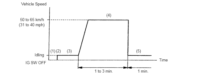
CONFIRMATION DRIVING PATTERN

A401588E01
0.729,0.052 1.698,0.313 0.969,0.26 10 false Vehicle Speed 0.688,0.594 1.646,0.813 0.958,0.219 10 false 50 to 65 km/h 0.646,0.771 1.583,1.021 0.938,0.25 10 false (31 to 40 mph) 1.188,1.813 1.583,2.021 0.396,0.208 10 false Idling 0.875,2.083 1.688,2.302 0.813,0.219 10 false IG SW OFF 3.24,2.375 3.938,2.583 0.698,0.208 10 false 1 to 3 min. 4.719,2.375 5.198,2.583 0.479,0.208 10 false 1 min. 5.458,1.99 5.906,2.188 0.448,0.198 10 false Time 4.667,1.677 4.958,1.896 0.292,0.219 10 false (5) 3.646,0.438 3.938,0.656 0.292,0.219 10 false (4) 2.292,1.677 2.583,1.896 0.292,0.219 10 false (3) 1.917,1.677 2.208,1.896 0.292,0.219 10 false (2) 1.729,1.677 2.021,1.896 0.292,0.219 10 false (1)

1.

Connect the hand-held tester to the DLC3.(1)

2.

Switch the hand-held tester from normal mode to check (test) mode.(2)

3.

Start the engine and warm it up with all accessory switches OFF.(3)

4.

Drive the vehicle at 50 to 65 km/h (31 to 40 mph) for 1 to 3 min. to warm up the oxygen sensor.(4)

5.

Let the engine idle for 1 min.(5)


HINT:
·

If you have no hand-held tester, do step (1) to (5) again.

·

If a malfunction exists, the check engine warning (CHK ENG) will light up during step (5).


NOTICE:

If the conditions in this test are not strictly followed, detection of the malfunction will not be possible. If you do not have a hand-held tester, turn the ignition switch OFF after performing steps (3) to (5), them perform steps (3) to (5) again.


CAUTION / NOTICE / HINT

HINT:

Read freeze frame data using hand-held tester. Because freeze frame records the engine conditions when the malfunction is detected. When troubleshooting, it is useful for determining whether the vehicle was running or stopped, the engine was warmed up or not, the air-fuel ratio was lean or rich, etc. at the time of the malfunction.


PROCEDURE

1.Are there any other codes (except DTC P0130) being output?
Result:
Proceed to
YES
NO


YES

Go to relevant DTC chart.

NO

2.Check oxygen sensor.
Result:
Proceed to
OK
NG


OK

3.Perform confirmation driving pattern.

NG

5.Check open and short in harness and connector between engine ECU and oxygen sensor.
3.Perform confirmation driving pattern.
Result:
Proceed to
GO


GO

4.Is DTC P0130 being output again?
Result:
Proceed to
YES
NO


YES

Check for intermittent problems.

NO

Check and replace engine ECU.

5.Check open and short in harness and connector between engine ECU and oxygen sensor.

OK

6.Check air induction system.

NG

Repair or replace harness or connector.

6.Check air induction system.
Result:
Proceed to
OK
NG


OK

7.Check LPG regurator primary prissure.

NG

Repair or replace induction system.

7.Check LPG regurator primary prissure.
Result:
Proceed to
OK
NG


OK

8.Check LPG carburetor.

NG

Check and repair LPG regurator, fuel pipe line and LPG solenoid.

8.Check LPG carburetor.
Result:
Proceed to
OK
NG


OK

Replace oxygen sensor.

NG

Repair or replace LPG carburetor.