1BZ-FPE ENGINE CONTROL ELECTRONIC CONTROLLED CARBURETOR SYSTEM P0335 Crankshaft Position Sensor Circuit Malfunction (NE Signal) P1335 Crankshaft Position Sensor Circuit Malfunction (During Engine Running)
DESCRIPTION
The distributor in the engine control system contains a pickup coil for NE signal.
The NE signal plate has 4 teeth on its outer circumference. The NE signal sensor generates 4 signals for every engine revolution. The engine ECU detects the engine speed by the NE signal.
| DTC No. | DTC Detecting Condition | Trouble Area |
|---|---|---|
| P0335/12 | No NE signal to ECU during cranking | ·
Open or short in NE circuit ·
Distributor ·
Engine ECU |
| No NE signal to ECU for 2.0 sec. or more at 1500 rpm or more. | ||
| P1335/13 | No crankshaft position sensor signal to engine ECU with engine speed 1,000 rpm or more | ·
Open or short in crankshaft position sensor circuit ·
Crankshaft position sensor ·
Starter ·
Engine ECU |
- Reference:
INSPECTION USING OSCILLOSCOPE
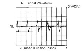
During cranking or idling, check the waveform between terminals NE+ and NE- of the engine ECU connector.
- HINT:
-
The correct waveform is as shown.
WIRING DIAGRAM
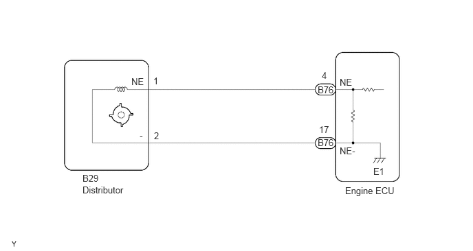
CAUTION / NOTICE / HINT
- HINT:
-
Read freed frame data using hand-held tester. Because freeze frame records the engine conditions when the malfunction is detected, when troubleshooting it is useful for determining whether the vehicle was running or stopped, the engine warmed up or not, the air-fuel ratio lean or rich, etc. at the time of the malfunction.
PROCEDURE
- Result:
Proceed to OK NG
OK
NG
- Result:
Proceed to OK NG
OK
NG
- Result:
Proceed to OK NG
OK
NG