Home › Engine / Hybrid System › 1BZ-FPE (ENGINE CONTROL) › ELECTRONIC CONTROLLED CARBURETOR SYSTEM › 2017.01–2021.01
RM2850E _51 Engine / Hybrid System _073136 1BZ-FPE ENGINE CONTROL _0355837 ELECTRONIC CONTROLLED CARBURETOR SYSTEM J

1BZ-FPE ENGINE CONTROL  ELECTRONIC CONTROLLED CARBURETOR SYSTEM  TE1 Terminal Circuit  


DESCRIPTION

Terminals TE1 are located in the check connector.

The check connector is located in the engine compartment. When these terminals are connected with the E1 terminal, the DTCs in the normal mode or test mode can be read from the check engine warning light in the combination meter.

WIRING DIAGRAM
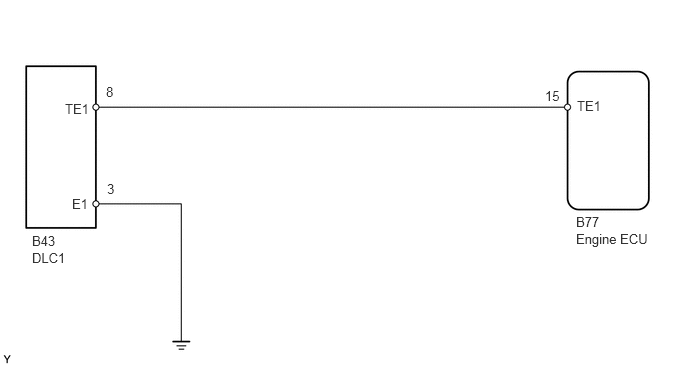
A120231E04
0.75,2.042 1.031,2.24 0.281,0.198 10 false E1 0.677,1.052 1.094,1.292 0.417,0.24 10 false TE1 0.333,2.427 0.813,2.625 0.479,0.198 10 false B43 5.677,0.917 5.896,1.125 0.219,0.208 10 false 15 6.01,1.021 6.427,1.24 0.417,0.219 10 false TE1 0.333,2.604 0.813,2.802 0.479,0.198 10 false DLC1 6,2.229 6.385,2.417 0.385,0.188 10 false B77 6,2.406 6.938,2.635 0.938,0.229 10 false Engine ECU 1.104,0.875 1.365,1.104 0.26,0.229 10 false 8 1.115,1.885 1.344,2.083 0.229,0.198 10 false 3

CAUTION / NOTICE / HINT

HINT:
·

If terminals TE1 are connected with terminal E1, the DTC is not output or the test mode is not activated.

·

Even though terminal TE1 is not connected with terminal E1, the check engine warning light blinks.

·

For the above phenomenon, the likely cause is open or short in the wire harness, or malfunction inside the engine ECU.


PROCEDURE
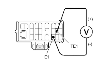
1.Check voltage between terminals TE1 and E1 of check connector.
A401604E01
1.563,1.802 1.771,1.281 true 2.302,1.458 1.906,1.063 true 1.479,1.833 1.792,2.031 0.313,0.198 10 false E1 2.354,1.469 2.802,1.698 0.448,0.229 10 false TE1 2.938,1.396 3.25,1.594 0.313,0.198 10 false (-) 2.927,0.552 3.24,0.75 0.313,0.198 10 false (+)

PREPARATION:

Turn the ignition switch ON.

CHECK:

Measure the voltage between terminals TE1 and E1 of the check connector.

OK:

Voltage: 9 - 14 V


Result:
Proceed to
OK
NG


OK

NG

2.Check continuity between terminal E1 of check connector and body ground.
Result:
Proceed to
OK
NG


OK

3.Check for open and short in harness and connector between terminals TE1 of engine ECU and check connector.

NG

Repair or replace harness or connector.

3.Check for open and short in harness and connector between terminals TE1 of engine ECU and check connector.

OK

NG

Repair or replace harness or connector.