1BZ-FPE ENGINE CONTROL ELECTRONIC CONTROLLED CARBURETOR SYSTEM Stop Light Switch Signal Circuit
DESCRIPTION
This signal is used to detect when the brakes have been applied. The ELS signal voltage is the same as the voltage supplied to the stop lights.
The ELS signal is used mainly to control the fuel cut-off engine speed (The fuel cut-off engine speed is reduced slightly when the vehicle is braking.).
WIRING DIAGRAM
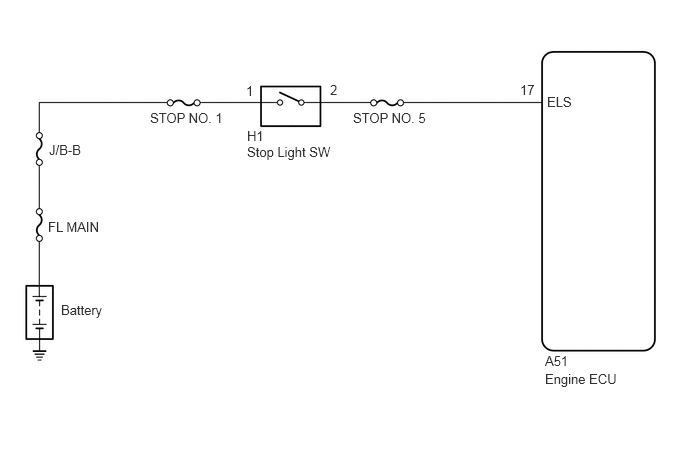
CAUTION / NOTICE / HINT
- NOTICE:
-
Inspect the fuses for circuits related to this system before performing the following inspection procedure.
- HINT:
-
Read freeze frame data using a hand-held tester. Because freeze frame records the engine conditions when the malfunction is detected. When troubleshooting, it is useful for determining whether the vehicle was running or stopped, the engine was warmed up or not, the air-fuel ratio was lean or rich, etc. at the time of the malfunction.
PROCEDURE
CHECK:
Check if the stop lights go on and off normally when the brake pedal is operated and released.
- Result:
Proceed to OK NG
OK
NG
When using hand-held tester:
PREPARATION:
Connect the hand-held tester to the DLC3.
Turn the ignition switch ON and push the hand-held tester main switch ON.
CHECK:
Read the STP signal on the hand-held tester.
| Brake Pedal | STP Signal |
|---|---|
| Depressed | ON |
| Released | OFF |
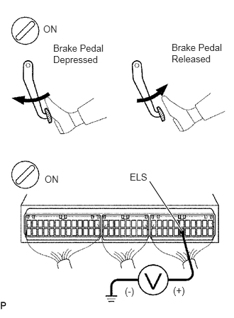
When not using hand-held tester:
PREPARATION:
Remove the side trim bracket.
Turn the ignition switch ON.
CHECK:
Check the voltage between terminal ELS of the engine ECU connector and body ground.
| Brake Pedal | Voltage |
|---|---|
| Depressed | 7.5 - 14 V |
| Released | Below 1.5 V |
- Result:
Proceed to OK NG
OK
NG
- Result:
Proceed to OK NG
OK
NG