1BZ-FPE ENGINE CONTROL IGNITION SYSTEM ON-VEHICLE INSPECTION
CAUTION / NOTICE / HINT
- NOTICE:
-
"Cold" and "Hot" in these sentences express the temperature of the coils themselves. "Cold" is from -10°C (14°F) to 50°C (122°F) and "Hot" is from 50°C (122°F) to 100°C (212°F).
PROCEDURE

 1.INSPECT IGNITER AND PERFORM SPARK TEST
Check that spark occurs
Disconnect the connector of LPG solenoidvalve.
Disconnect the high-tension cord from the spark plug.
Remove the spark plug.
Install the spark plug to the high-tension cord.
Ground the spark plug.
See if spark occurs while the engine is being cranked.
- NOTICE:
-
To prevent fuel from being injected from the carburetor during this test, crank the engine for no more than 5 to 10 seconds at a time.
Perform the spark test in accordance with the following procedure.
Check that the connectors of the ignition coil, igniter and distributor wire harness are securely connected.
- Result:
Result Proceed to NG Connect securely OK Go to next step
Check resistance of high-tension cord.
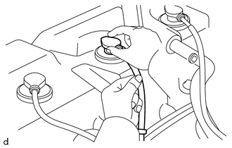
Remove the high-tension cord.
- NOTICE:
- ·
Disconnect the high-tension cord at the rubber boot.
·Do not pull out the high-tension cord.
·Pulling out or bending the cord may damage the conductor inside.
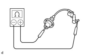
Measure the high-tension cord resistance.
- Maximum resistance:
25 kW per cord
- Result:
Result Proceed to More then 25 kW Replace high-tension cord(s) 25 kW or less Go to next step
Check the power supply to the ignition coil.
Turn the ignition switch to ON
Check that there is battery voltage at the positive (+) ignition coil terminal.
- Result:
Result Proceed to NG Check wiring between ignition switch and ignition coil OK Go to next step
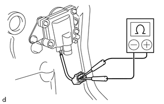
Check resistance of ignition coils.
Disconnect the high-tension cord from the ignition coil.
Disconnect the connector.
Measure the resistance between the positive (+) and negative (-) terminals.
- Primary coil resistance:
Condition Specified Condition Cold 0.36 to 0.55 W Hot 0.45 to 0.65 W
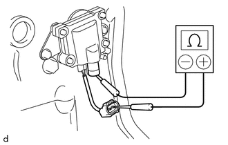
Measure the resistance between the positive (+) and high-tension terminals.
- Secondary coil resistance:
Condition Specified Condition Cold 9.0 to 15.4 kW Hot 11.4 to 18.1 kW
- Result:
Result Proceed to NG Replace ignition coil(s) OK Go to next step
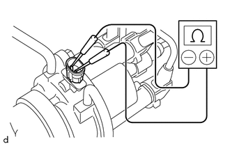
Check resistance of signal generator (pickup coil).
Disconnect the connector.
Measure the resistance between the terminals.
- Primary coil resistance:
Condition Specified Condition Cold 135 to 220 W Hot 175 to 255 W
- Result:
Result Proceed to NG Replace distributor housing assembly OK Go to next step
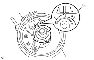
Check air gap of distributor.
Remove the distributor cap.
Remove the rotor and dust-proof cover.
Using a feeler gauge, measure the air gap between the signal rotor and pickup coil projection.
- Air gap:
0.2 to 0.4 mm (0.008 to 0.016 in.)
| *a | Air Gap |
- Result:
Result Proceed to NG Replace distributor housing assembly OK Go to next step
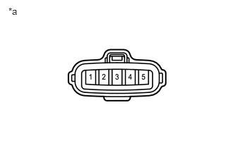
Check the power supply to the igniter.
Turn the ignition switch to ON.
Measure the voltage between the terminal 3 and the body ground.
- Result:
Result Proceed to NG Check wiring between ignition switch and ignition coil OK Go to next step
| *a | Component without Harness Connected (Igniter) |
Check the wire harness between igniter and ignition coil.
Measure the resistance of the wire harnessside connectors.
- Standard resistance:
Tester Connection Specified Condition I15-5 - I16-2 Below 1 W
- Result:
Result Proceed to NG Repair wiring between igniter and ignition coil OK Go to next step
Check the IGT and IGF signal circuits.
- Result:
Result Proceed to NG Repair wiring between igniter and ECM OK Check ECM
19100P
2.INSPECT SPARK PLUG
- NOTICE:
- ·
Never use a wire brush for cleaning.
·Never attempt to adjust the electrode gap on used spark plug.
·Spark plug should be replaced every 100000 km (60000 miles).
Disconnect the high-tension cords from the spark plugs.
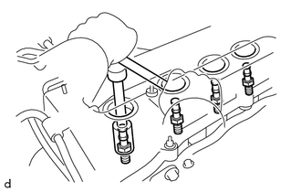
Using a plug wrench, remove the 4 spark plugs.
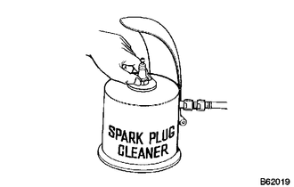
Using a spark plug cleaner, clean the spark plug.
- Air pressure:
Below 588 kpa (6 kgf/cm2, 85 psi)
- Duration:
20 seconds or less
- HINT:
-
If there are traces of oil, remove them with gasoline before using the spark plug cleaner.
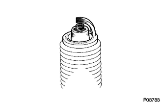
Check the spark plug for electrode wear, thread damage and insulator damage.
If abnormal, replace the spark plug.
- Recommended spark plug:
Manufacturer Product DENSO DK16R-B5
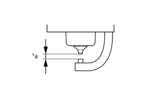
Inspect the electrode gaps.
- Standard electrode gap:
0.4 to 0.5 mm (0.016 to 0.020 in.)
- Maximum electrode gap:
0.70 mm (0.0276 in.)
| *a | Spark Plug Electrode Gap |
If the gap is greater than maximum, replace the spark plug.
Using a plug wrench, reinstall the 4 spark plugs.
- Torque:
20 N*m (204 kgf*cm, 15 ft.*lbf)
Reconnect the high-tension cords to the spark plugs.