RM2850E
_52
Drivetrain
_073139
A444E AUTOMATIC TRANSMISSION / TRANSAXLE
_0355865
AUTOMATIC TRANSMISSION SYSTEM
U
A444E AUTOMATIC TRANSMISSION / TRANSAXLE AUTOMATIC TRANSMISSION SYSTEM TERMINALS OF ECM
- HINT:
-
Each ECU terminal's standard voltage is shown in the table below.
-
In the table, first follow the information under "Condition". Look under " Terminal No. (Symbol)" for the terminals to be inspected. The standard voltage between the terminals is shown under "Specified Condition".
-
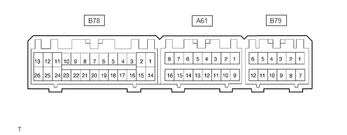
Use the illustration above as a reference for the ECU terminals.
TCM
1.74,0.313 2.156,0.531
0.417,0.219
3.969,0.323 4.385,0.542
0.417,0.219
5.5,0.313 5.917,0.531
0.417,0.219
1.823,0.344 2.198,0.542
0.375,0.198
10
false
B78
4.052,0.344 4.438,0.542
0.385,0.198
10
false
A61
5.573,0.344 5.958,0.542
0.385,0.198
10
false
B79
| Terminal No. (Symbol) | Wiring Color | Terminal Description | Condition | Specified Condition |
|---|---|---|---|---|
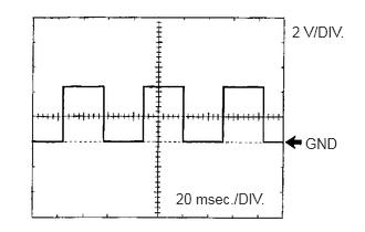
| B78-1 (NE) - B79-2 (E) | B - W-B | Engine speed signal | Engine idle speed | Pulse generation (see waveform 1) |
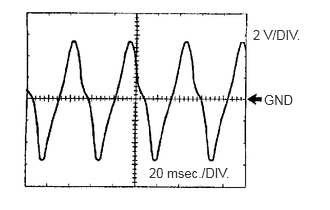
| B78-3 (SP2+) - B78-16 (SP2-) | V - P | No. 2 vehicle speed sensor (SP2) signal | Vehicle speed 20 km/h (12 mph) | Pulse generation (see waveform 2) |
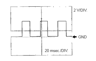
| B78-4 (SPD1) - B79-2 (E) | V - W-B | Speed signal | Vehicle speed 20 km/h (12 mph) | Pulse generation (see waveform 3) |
| B78-6 (OIL2) - B78-20 (E2) | B - BR | No. 2 ATF temperature sensor signal | ATF temperature: 20 to 80°C (68 to 176°F) or more | 0.4 to 3.5 V |
| B78-9 (DGLP) - B79-2 (E) | P - W-B | Diagnostic indicator light(O/D OFF indicator light) | Transmission control SW ON | Below 1 V |
| B78-11 (ST) - B79-2 (E) | G - W-B | ST solenoid signal | D position (2rd gear ←→ 3rd gear) | Below 1 V ←→ 11 to 14 V |
| B78-12 (S2) - B79-2 (E) | G - W-B | S2 solenoid signal | 1st gear | Below 1 V |
| 2nd gear | 11 to 14 V | |||
| B78-13 (S1) - B79-2 (E) | G - W-B | S1 solenoid signal | 1st gear | 11 to 14 V |
| 3rd gear | Below 1 V | |||
| B78-24 (SL) - B79-2 (E) | R - W-B | SL solenoid signal | Lock-up ON | 11 to 14 V |
| Lock-up OFF | Below 1 V | |||
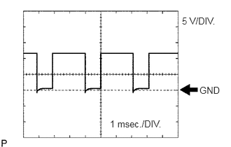
| B78-26 (SLT+) - B78-25 (SLT-) | GR - GR | SLT solenoid signal | Engine idle speed | Pulse generation (see waveform 4) |
| A61-6 (OD2) - B79-2 (E) | P - W-B | Transmission control SW signal | Transmission control SW ON | Below 1 V |
| Transmission control SW OFF | 11 to 14 V | |||
| A61-8 (DG) - B79-2 (E) | P - W-B | Terminal DG of DLC3 | Connect terminal 13(TC) and 4(CG) of DLC3 | Below 1 V |
| Disconnect terminal 13(TC) and 4(CG) of DLC3 | 11 to 14 V | |||
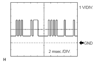
| A61-11 (ECT-) - B79-2 (E) | G - W-B | Communication line (between ECM and TCM) | Engine idle speed | Pulse generation (see waveform 5) |
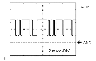
| A61-12 (ECT+) - B79-2 (E) | R - W-B | Communication line (between ECM and TCM) | Engine idle speed | Pulse generation (see waveform 6) |
| A61-13 (EFI-) - B79-2 (E) | GR - W-B | Communication line (between ECM and TCM) | Engine idle speed | Pulse generation (see waveform 5) |
| A61-14 (EFI+) - B79-2 (E) | P - W-B | Communication line (between ECM and TCM) | Engine idle speed | Pulse generation (see waveform 6) |
| A61-15 (THO) - B78-20 (E2) | LG - BR | No. 1 ATF temperature sensor signal | ATF temperature: 20 to 80°C (68 to 176°F) or more | 1.1 to 4.1 V |
| B79-1 (IG) - B79-2 (E) | B - W-B | Ignition switch | Ignition switch ON | 11 to 14 V |
| B79-3 (P) - B79-2 (E) | R - W-B | P shift position switch signal | Ignition switch ON and shift position in P | 11 to 14 V |
| Ignition switch ON and shift position not in P | Below 1 V | |||
| B79-4 (N) - B79-2 (E) | R - W-B | N shift position switch signal | Ignition switch ON and shift position in N | 11 to 14 V |
| Ignition switch ON and shift position not in N | Below 1 V | |||
| B79-6 (L) - B79-2 (E) | R - W-B | L shift position switch signal | Ignition switch ON and shift position in L | 11 to 14 V |
| Ignition switch ON and shift position not in L | Below 1 V | |||
| B79-9 (R) - B79-2 (E) | Y - W-B | R shift position switch signal | Ignition switch ON and shift position in R | 11 to 14 V |
| Ignition switch ON and shift position not in R | Below 1 V | |||
| B79-11 (2) - B79-2 (E) | Y - W-B | 2 shift position switch signal | Ignition switch ON and shift position in 2 | 11 to 14 V |
| Ignition switch ON and shift position not in 2 | Below 1 V | |||
| B79-12 (STP) - B79-2 (E) | G - W-B | Stop light switch signal | Ignition switch ON and brake pedal is depressed | 11 to 14 V |
| Ignition switch ON and brake pedal is released | Below 1 V |
Waveform 1
2.75,0.219 3.375,0.406
0.625,0.188
10
false
2 V/DIV.
1.656,1.792 2.677,1.979
1.021,0.188
10
false
20 msec./DIV.
2.875,1.271 3.375,1.458
0.5,0.188
10
false
GND
| Item | Content |
|---|---|
| Symbol | NE - E |
| Tool Setting | 2 V/DIV., 20 msec./DIV. |
| Condition | Engine idle speed |
Waveform 2
2.635,0.281 3.323,0.458
0.688,0.177
10
false
2 V/DIV.
2.75,0.958 3.292,1.135
0.542,0.177
10
false
GND
1.552,1.719 2.552,1.906
1,0.188
10
false
20 msec./DIV.
| Item | Content |
|---|---|
| Symbol | SP2+ - SP2- |
| Tool Setting | 2 V/DIV., 20 msec./DIV. |
| Condition | Vehicle speed 20 km/h (12 mph) |
Waveform 3
2.635,0.281 3.344,0.469
0.708,0.188
10
false
2 V/DIV.
2.802,1.24 3.292,1.417
0.49,0.177
10
false
GND
1.604,1.729 2.615,1.906
1.01,0.177
10
false
20 msec./DIV.
| Item | Content |
|---|---|
| Symbol | SPD1 - E |
| Tool Setting | 2 V/DIV., 20 msec./DIV. |
| Condition | Vehicle speed 20 km/h (12 mph) |
Waveform 4
2.708,0.229 3.396,0.427
0.688,0.198
10
false
5 V/DIV.
2.969,1.26 3.365,1.448
0.396,0.188
10
false
GND
1.635,1.76 2.573,1.958
0.938,0.198
10
false
1 msec./DIV.
| Item | Content |
|---|---|
| Symbol | SLT+ - SLT- |
| Tool Setting | 5 V/DIV., 1 msec./DIV. |
| Condition | Engine idle speed |
Waveform 5
2.771,0.177 3.385,0.365
0.615,0.188
10
false
1 V/DIV.
2.948,1.438 3.385,1.615
0.438,0.177
10
false
GND
1.708,1.729 2.667,1.938
0.958,0.208
10
false
2 msec./DIV.
| Item | Content |
|---|---|
| Symbol | EFI- - E, ECT- - E |
| Tool Setting | 1 V/DIV., 2 msec./DIV. |
| Condition | Engine idle speed |
Waveform 6
2.781,0.167 3.375,0.365
0.594,0.198
10
false
1 V/DIV.
1.75,1.74 2.667,1.948
0.917,0.208
10
false
2 msec./DIV.
2.969,1.448 3.385,1.646
0.417,0.198
10
false
GND
| Item | Content |
|---|---|
| Symbol | EFI+ - E, ECT+ - E |
| Tool Setting | 1 V/DIV., 2 msec./DIV. |
| Condition | Engine idle speed |