A444E AUTOMATIC TRANSMISSION / TRANSAXLE AUTOMATIC TRANSMISSION SYSTEM 65 Shift Solenoid Valve ST Electrical Malfunction
DESCRIPTION
Shift solenoid valve ST is switched OFF-ON-OFF in accordance with signals from the TCM when up-shifting and down-shifting between the 2nd and 3rd gears. This reduces the shock of gear shifting between these positions.
| DTC No. | DTC Detection Condition | Trouble Area |
|---|---|---|
| 65 | TCM detects open or short in solenoid valve ST circuit (once) when solenoid valve ST is operated. (1 trip detection logic) | ·
Short in shift solenoid valve ST circuit ·
Shift solenoid valve ST ·
Transmission wire ·
TCM |
MONITOR DESCRIPTION
If the TCM detects an open or short in the shift solenoid valve ST circuit, the TCM interprets this as a fault in the shift solenoid valve ST or its circuit. The TCM will store the DTC.
WIRING DIAGRAM
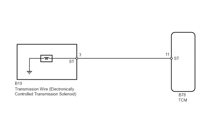
PROCEDURE
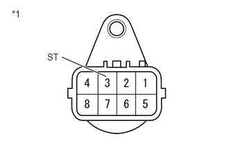
Disconnect the transmission wire connector.
Measure the resistance according to the value(s) in the table below.
- Standard Resistance:
Tester Connection Condition Specified Condition 3 (ST) - Body ground 20°C (68°F) 11 to 15 Ω
| *1 | Component without harness connected:
(Transmission Wire) |
- Result:
Proceed to OK NG
OK
NG
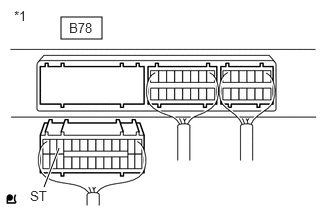
Disconnect the TCM connector.
Measure the resistance according to the value(s) in the table below.
- Standard Resistance:
Tester Connection Condition Specified Condition B78-11 (ST) - Body ground 20°C (68°F) 11 to 15 Ω
| *1 | Rear view of wire harness connector:
(to TCM) |
- Result:
Proceed to OK NG
OK
NG
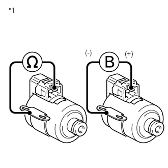
Remove shift solenoid valve ST.
Measure the resistance according to the value(s) in the table below.
- Standard Resistance:
Tester Connection Condition Specified Condition 1 - Solenoid body 20°C (68°F) 11 to 15 Ω
| *1 | Shift solenoid valve (ST) |
Connect the battery's positive (+) lead to the terminal of the solenoid connector, and the negative (-) lead to the solenoid body.
Check the operating noise of the solenoid valve.
- OK:
The solenoid makes an operating sound.
- Result:
Proceed to OK NG
OK
NG