RM2850E
_52
Drivetrain
_073139
A444E AUTOMATIC TRANSMISSION / TRANSAXLE
_0355865
AUTOMATIC TRANSMISSION SYSTEM
C
A444E AUTOMATIC TRANSMISSION / TRANSAXLE AUTOMATIC TRANSMISSION SYSTEM 88 Communication Malfunction (ECM and TCM)
DESCRIPTION
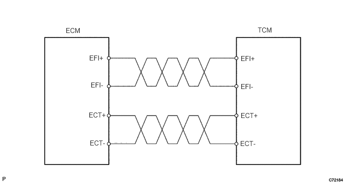
TCM receives accelerator position and idling signal from ECM. And TCM sends lock-up condition and shift position to ECM.
| DTC No. | DTC Detection Condition | Trouble Area |
|---|---|---|
| 88 | When all conditions below remain for 5 seconds or more (1 trip detection logic):
1.
Engine speed is 500rpm or more. 2.
Communication circuit malfunction with ECM |
·
Open or short in communication circuit between ECM and TCM ·
ECM ·
TCM |
WIRING DIAGRAM
1.365,0.552 1.823,0.75
0.458,0.198
10
false
ECM
1.854,1.125 2.313,1.323
0.458,0.198
10
false
EFI+
1.885,1.688 2.344,1.885
0.458,0.198
10
false
EFI-
1.844,2.313 2.302,2.51
0.458,0.198
10
false
ECT+
1.865,2.896 2.323,3.094
0.458,0.198
10
false
ECT-
5,1.135 5.458,1.333
0.458,0.198
10
false
EFI+
5.354,0.542 5.813,0.74
0.458,0.198
10
false
TCM
5,1.719 5.458,1.917
0.458,0.198
10
false
EFI-
5,2.323 5.458,2.521
0.458,0.198
10
false
ECT+
4.99,2.906 5.448,3.104
0.458,0.198
10
false
ECT-
PROCEDURE
1.CHECK TCM (ECM - TCM SIGNAL)
a.
1.635,0.26 2.063,0.479
0.427,0.219
2.281,0.26 2.708,0.479
0.427,0.219
1.479,1.5 1.813,1.052
true
2.135,1.521 1.969,1.063
true
2.938,1.479 2.635,0.865
true
0.125,0.104 0.438,0.302
0.313,0.198
10
false
*1
1.729,0.281 2.104,0.479
0.375,0.198
10
false
A61
2.385,0.281 2.76,0.479
0.375,0.198
10
false
B79
1.344,1.542 1.719,1.74
0.375,0.198
10
false
EFI-
2.01,1.552 2.427,1.75
0.417,0.198
10
false
ECT-
2.917,1.531 3.177,1.729
0.26,0.198
10
false
E
2.771,2.49 3.406,2.688
0.635,0.198
10
false
1 V/DIV.
2.99,3.781 3.396,3.979
0.406,0.198
10
false
GND
1.802,4.052 2.698,4.26
0.896,0.208
10
false
2 msec./DIV.
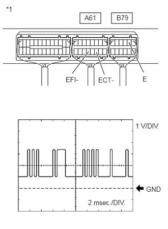
During idling, check the waveform of the TCM connectors using an oscilloscope.
- OK:
Refer to illustration
Item Content Tester Connection A61-13 (EFI-) - B79-2 (E)
A61-11 (ECT-) - B79-2 (E)Tool Setting 1 V/DIV., 2 msec./DIV. Condition Idling
| *1 | Component with harness connected:
(TCM) |
b.
1.615,0.313 2.052,0.521
0.438,0.208
2.25,0.313 2.688,0.521
0.438,0.208
1.552,1.51 1.729,1.052
true
2.104,1.51 1.875,1.063
true
2.833,1.5 2.635,0.865
true
0.094,0.083 0.406,0.281
0.313,0.198
10
false
*1
1.708,0.333 2.063,0.531
0.354,0.198
10
false
A61
2.344,0.344 2.729,0.542
0.385,0.198
10
false
B79
1.292,1.542 1.677,1.74
0.385,0.198
10
false
EFI+
2.01,1.552 2.396,1.75
0.385,0.198
10
false
ECT+
2.833,1.531 3.073,1.729
0.24,0.198
10
false
E
2.771,2.531 3.406,2.729
0.635,0.198
10
false
1 V/DIV.
1.729,4.042 2.667,4.229
0.938,0.188
10
false
2 msec./DIV.
2.948,3.781 3.375,3.979
0.427,0.198
10
false
GND
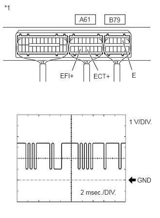
During idling, check the waveform of the TCM connectors using an oscilloscope.
- OK:
Refer to illustration
Item Content Tester Connection A61-14 (EFI+) - B79-2 (E)
A61-12 (ECT+) - B79-2 (E)Tool Setting 1 V/DIV., 2 msec./DIV. Condition Idling
| *1 | Component with harness connected:
(TCM) |
- Result:
Proceed to OK NG
OK
REPLACE TCM
NG
2.CHECK WIRE HARNESS (ECM - TCM)
2.CHECK WIRE HARNESS (ECM - TCM)
a.
Disconnect the ECM connector.
b.
Disconnect the TCM connector.
c.
Measure the resistance according to the value(s) in the table below.
- Standard Resistance:
Tester Connection Condition Specified Condition A54-24 (ECT-) - A61-11 (ECT-) Always Below 1Ω A54-25 (ECT+) - A61-12 (ECT+) Always Below 1Ω A54-30 (EFI-) - A61-13 (EFI-) Always Below 1Ω A54-31 (EFI+) - A61-14 (EFI+) Always Below 1Ω A54-24 (ECT-) and A61-11 (ECT-) - Body ground Always 10kΩ or higher A54-25 (ECT+) and A61-12 (ECT+) - Body ground Always 10kΩ or higher A54-30 (EFI-) and A61-13 (EFI-) - Body ground Always 10kΩ or higher A54-31 (EFI+) and A61-14 (EFI+) - Body ground Always 10kΩ or higher
- Result:
Proceed to OK NG
OK
REPLACE ECM
NG
REPAIR OR REPLACE HARNESS AND CONNECTOR