Home › Drivetrain › A444E (AUTOMATIC TRANSMISSION / TRANSAXLE) › AUTOMATIC TRANSMISSION SYSTEM › 2017.01–2021.01
RM2850E _52 Drivetrain _073139 A444E AUTOMATIC TRANSMISSION / TRANSAXLE _0355865 AUTOMATIC TRANSMISSION SYSTEM J

A444E AUTOMATIC TRANSMISSION / TRANSAXLE  AUTOMATIC TRANSMISSION SYSTEM  Park / Neutral Position Switch Circuit  


DESCRIPTION

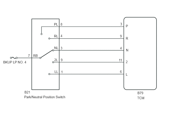
The Park/Neutral Position (PNP) switch detects the shift lever position and sends signals to the TCM.

WIRING DIAGRAM
C374514E01
0.135,2.5 1.26,2.677 1.125,0.177 10 false BKUP LP NO. 4 1.167,2.229 1.385,2.406 0.219,0.177 10 false 7 1.385,2.229 1.667,2.406 0.281,0.177 10 false RB 2.25,0.927 2.531,1.104 0.281,0.177 10 false PL 2.25,1.417 2.531,1.594 0.281,0.177 10 false RL 2.26,1.906 2.542,2.083 0.281,0.177 10 false NL 2.26,2.406 2.542,2.583 0.281,0.177 10 false 2L 2.271,2.896 2.552,3.073 0.281,0.177 10 false LL 1.021,3.75 1.396,3.927 0.375,0.177 10 false B21 1.01,3.948 2.938,4.146 1.927,0.198 10 false Park/Neutral Position Switch 2.521,0.927 2.802,1.104 0.281,0.177 10 false 8 2.521,1.406 2.802,1.583 0.281,0.177 10 false 4 2.521,1.917 2.802,2.094 0.281,0.177 10 false 3 2.531,2.406 2.813,2.583 0.281,0.177 10 false 9 2.542,2.906 2.823,3.083 0.281,0.177 10 false 1 5.01,0.917 5.292,1.094 0.281,0.177 10 false 3 5,1.417 5.281,1.594 0.281,0.177 10 false 9 5,1.917 5.281,2.094 0.281,0.177 10 false 4 4.948,2.417 5.229,2.594 0.281,0.177 10 false 11 5,2.896 5.281,3.073 0.281,0.177 10 false 6 5.24,1 5.521,1.177 0.281,0.177 10 false P 5.25,2 5.531,2.177 0.281,0.177 10 false N 5.24,1.51 5.521,1.688 0.281,0.177 10 false R 5.24,2.49 5.521,2.667 0.281,0.177 10 false 2 5.24,3.01 5.521,3.188 0.281,0.177 10 false L 5.719,3.99 6.24,4.167 0.521,0.177 10 false TCM 5.729,3.781 6.135,3.958 0.406,0.177 10 false B79

CAUTION / NOTICE / HINT

NOTICE:

Inspect the fuses for circuits related to this system before performing the following procedure.


PROCEDURE
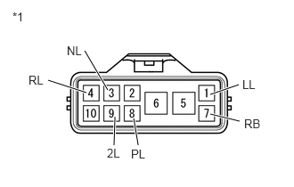
1.INSPECT PARK/NEUTRAL POSITION SWITCH
a.
C174454E04
0.99,0.594 1.26,1.052 true 0.563,0.938 1.01,1.083 true 1.344,1.365 1.333,1.698 true 1.563,1.385 1.615,1.698 true 2.458,1.104 2.792,0.99 true 2.458,1.333 2.802,1.417 true 0.146,0.115 0.458,0.313 0.313,0.198 10 false *1 0.781,0.51 1.094,0.708 0.313,0.198 10 false NL 0.333,0.854 0.646,1.052 0.313,0.198 10 false RL 1.25,1.708 1.563,1.906 0.313,0.198 10 false 2L 1.531,1.719 1.844,1.917 0.313,0.198 10 false PL 2.833,0.906 3.146,1.104 0.313,0.198 10 false LL 2.854,1.365 3.167,1.563 0.313,0.198 10 false RB

Disconnect the B21 park/neutral position switch connector.


b.

Measure the resistance according to the value(s) in the table below.

Standard Resistance:
Tester Connection Switch Condition Specified Condition
7(RB) - 8(PL) Shift lever in P Below 1 Ω
Shift lever is not in P 10 kΩ or higher
4(RL) - 7(RB) Shift lever in R Below 1 Ω
Shift lever is not in R 10 kΩ or higher
3(NL) - 7(RB) Shift lever in N Below 1 Ω
Shift lever is not in N 10 kΩ or higher
7(RB) - 9(2L) Shift lever in 2 Below 1 Ω
Shift lever is not in 2 10 kΩ or higher
1(LL) - 7(RB) Shift lever in L Below 1 Ω
Shift lever is not in L 10 kΩ or higher


Text in Illustration
*1 Component without harness connected:
(Park/Neutral Position Switch)


Result:
Proceed to
OK
NG


OK

2.CHECK HARNESS AND CONNECTOR (BATTERY - TCM)

NG

REPLACE PARK/NEUTRAL POSITION SWITCH

2.CHECK HARNESS AND CONNECTOR (BATTERY - TCM)
a.
C174765E08
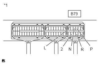
2.323,0.354 2.75,0.583 0.427,0.229 1.573,1.573 2.354,0.979 true 2.146,1.583 2.438,1.167 true 2.427,1.573 2.531,0.969 true 2.771,1.594 2.604,1.167 true 3.063,1.563 2.615,0.979 true 0.135,0.094 0.448,0.292 0.313,0.198 10 false *1 2.406,0.385 2.76,0.563 0.354,0.177 10 false B79 1.49,1.552 1.74,1.75 0.25,0.198 10 false L 2.063,1.594 2.313,1.792 0.25,0.198 10 false 2 2.333,1.594 2.583,1.792 0.25,0.198 10 false N 2.75,1.604 3,1.802 0.25,0.198 10 false R 3.063,1.594 3.313,1.792 0.25,0.198 10 false P

Turn the ignition switch to ON.


b.

Measure the voltage according to the value(s) table below.

Standard Voltage:
Tester Connection Switch Condition Specified Condition
B79-3(P) - Body ground
·

Ignition switch ON

·

Shift lever in P


11 to 14 V
·

Ignition switch ON

·

Shift lever is not in P


Below 1 V
B79-9(R) - Body ground
·

Ignition switch ON

·

Shift lever in R


11 to 14 V*
·

Ignition switch ON

·

Shift lever is not in R


Below 1 V
B79-4(N) - Body ground
·

Ignition switch ON

·

Shift lever in N


11 to 14 V
·

Ignition switch ON

·

Shift lever is not in N


Below 1 V
B79-11(2) - Body ground
·

Ignition switch ON

·

Shift lever in 2


11 to 14 V
·

Ignition switch ON

·

Shift lever is not in 2


Below 1 V
B79-6(L) - Body ground
·

Ignition switch ON

·

Shift lever in L


11 to 14 V
·

Ignition switch ON

·

Shift lever is not in L


Below 1 V


Text in Illustration
*1 Component with harness connected:
(TCM)

HINT:

*: The voltage will drop slightly due to the illumination of the back-up light.


Result:
Proceed to
OK
NG


OK

PROCEED TO NEXT SUSPECTED AREA SHOWN IN PROBLEM SYMPTOMS TABLE

NG

REPAIR OR REPLACE HARNESS OR CONNECTOR