A444E AUTOMATIC TRANSMISSION / TRANSAXLE AUTOMATIC TRANSMISSION UNIT INSPECTION
PROCEDURE

 34625
1.INSPECT NO.1 OVERDRIVE BRAKE FLANGE
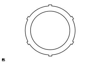
Using a micrometer, check the thickness of the No.1 overdrive brake flange.
- Standard thickness:
4.9 to 5.0 mm (0.1929 to 0.1969 in.)
- Limit thickness:
5.0 mm (0.1969 in.)
- NOTICE:
-
If the value is over the limit, replace the No.1 overdrive brake flange with a new one.
35677B
2.INSPECT OVERDRIVE BRAKE CLUTCH DISC
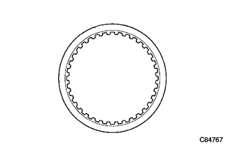
Check whether the sliding surfaces of the discs, the plates, and the flange are worn or burnt. If necessary, replace them.
- NOTICE:
- ·
If the linings of the discs are peeled off or discolored, or even a part of the printed numbers is damaged, replace all discs.
·Before assembling new discs, soak them in ATF for at least 2 hours.
34622
3.INSPECT OVERDRIVE BRAKE PISTON
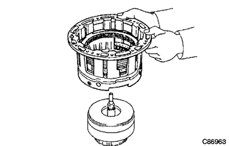
Install the overdrive case sub-assembly to the front clutch assembly.
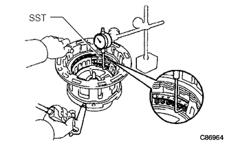
Install the SST to the dial indicator, and then set them to the overdrive support assembly vertically.
- SST
- 09350-36010 (09350-06110)
- NOTICE:
-
Do not let the SST touch except the piston.
Make sure the overdrive brake piston moves smoothly when applying compressed air to the oil hole of the overdrive case.
- Standard:
1.25 to 1.85 mm (0.0492 to 0.0728 in.)
- NOTICE:
-
Measure it at several positions and take the average. If the value is over the limit, check the clutch disc, plate and brake flange, and then replace the defective parts.
Remove the overdrive support assembly from the direct clutch assembly.
34101
4.INSPECT OVERDRIVE CASE SUB-ASSEMBLY
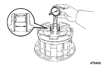
Using a dial indicator, measure the inside diameter of the overdrive case sub-assembly bushing.
- Standard inside diameter:
33.10 to 33.15 mm (1.3031 to 1.3051 in.)
- NOTICE:
-
Measure it at several positions and take the average. If the inside diameter is greater than the inside diameter , replace the overdrive case sub-assembly.
35790A
5.INSPECT 1 WAY CLUTCH ASSEMBLY
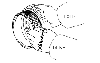
Hold the 1 way clutch assembly, and check that the front planetary turns freely counterclockwise and locks clockwise.
35720
6.INSPECT FRONT PLANETARY GEAR ASSEMBLY
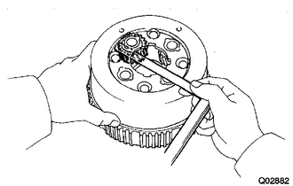
Using a thickness gauge, check the thrust clearance oh the each pinion gear of the front planetary gear assembly .
- Standard clearance:
0.20 to 0.59 mm (0.0079 to 0.0232 in.)
- Limit clearance:
0.8 mm (0.0315 in.)
- NOTICE:
-
If the clearance is greater than the standard clearance, replace the front planetary gear assembly.
35073
7.INSPECT OUTPUT SHAFT SUB-ASSEMBLY
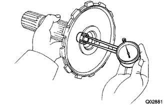
Using a dial indicator, measure the inside diameter of the output shaft sub assembly bushing.
- Standard inside diameter:
17.000 to 17.021 mm (0.6693 to 0.6701 in.)
- Limit inside diameter:
17.07 mm (0.672 in.)
- NOTICE:
-
Measure it at several positions and take the average. If the clearance is greater than the inside diameter, replace the output shaft sub-assembly.
35760
8.INSPECT REAR PLANETARY GEAR ASSEMBLY
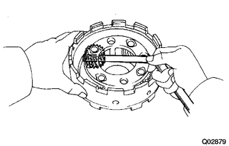
Using a thickness gauge, measure the rear planetary gear assembly pinion thrust clearance.
- Standard clearance:
0.20 to 0.59 mm (0.0079 to 0.0232 in.)
- Limit clearance:
0.8 mm (0.0315 in.)
- NOTICE:
-
If the value is over the limit, replace the rear planetary gear assembly with a new one.
35677A
9.INSPECT 1ST & REVERSE BRAKE CLUTCH DISC
Check whether the sliding surfaces of the discs, the plates, and the flange are worn or burnt. If necessary, replace them.
- NOTICE:
- ·
If the linings of the discs are peeled off or discolored, or even a part of the printed numbers is damaged, replace all discs.
·Before assembling new discs, soak them in ATF for at least 2 hours.
35068
10.INSPECT 1ST & REVERSE BRAKE RETURN SPRING SUB-ASSEMBLY
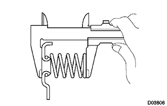
Using vernier calipers, measure the free length of the spring together with the spring seat.
- Standard free length:
17.60 mm (0.6929 in.)
- CAUTION:
-
If the free length is shorter than the standard free length, replace the 1st & reverse brake return spring sub-assembly.
35623H
11.INSPECT 1ST & REVERSE BRAKE PISTON
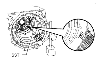
Set a SST and dial indicator as show in the illustration.
- SST
- 09350-36010 (09350-06120, 09350-06130)
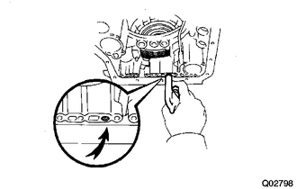
Measure the stroke while applying and releasing compressed air as show in the illustration.
If the piston stroke is still outside the standard even after reassembly, select another flange.
- Standard:
3.30 to 3.80 mm (0.1299 to 0.1496 in.)
- HINT:
flange thickness mark 35676-60050 6.65 mm (0.2618 in.) E 35676-60060 7.05 mm (0.2776 in.) F 35676-60070 7.45 mm (0.2933 in.) G
12.INSPECT CENTER SUPPORT ASSEMBLY
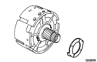
Install the center support washer to the center support assembly.
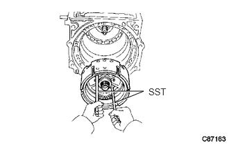
Using a SST, align the 3 oil holes and bolt installation holes with the automatic transmission case, and then install the center support assembly.
- SST
- 09350-36010 (09350-06140)
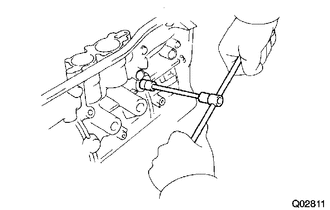
Install the center support assembly with the 3 bolts.
- Torque:
25 N*m (255 kgf*cm, 18 ft.*lbf)
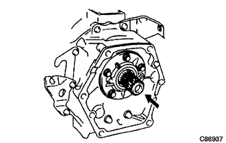
Push the output shaft with the power of 5 to 10 kgf.cm.
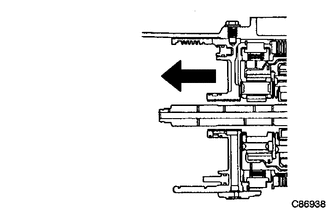
Pull on the center support assembly with the power of 5 to 10 kgf.cm.
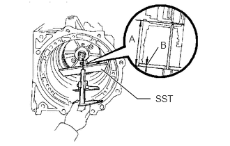
Using a SST and vernier caliper, measure the dimension (A) of the show in the illustration.
- SST
- 09350-36010 (09350-06090)
- HINT:
-
C lenghts = A lenghts - B lenghts (SST thickness)
Remove the 3 center support set overdrive case & transmission case set bolts.
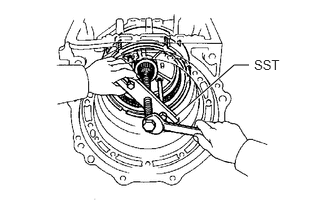
Using a SST, remove the center support assembly.
- SST
- 09350-36010 (09350-06140)
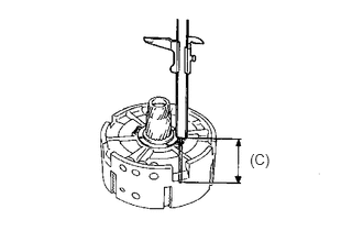
Using a vernier caliper, measure the dimension (C) of the show in the illustration.
If the least is still outside the standard even after reassembled, select another washer.
- Standard:
0.3 to 0.7 mm (0.0118 to 0.0276 in.)
- Limit:
0.7 mm (0.0276 in.)
- HINT:
center support washers thickness 90209-52005 1.5 mm (0.0591 in.) 90209-52006 1.8 mm (0.0709 in.) 90209-52007 2.1 mm (0.0827 in.) 90209-52008 2.4 mm (0.0945 in.) 90209-52009 2.7 mm (0.1063 in.)
13.INSPECT FRONT CLUTCH ASSEMBLY
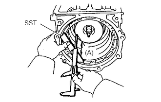
Using a SST and vernier caliper, measure the dimension (A) of the show in the illustration.
- SST
- 09350-36010 (09350-06090)
14.INSPECT INPUT SHAFT ENDPLAY
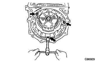
Install the 3 set bolts.
- Torque:
25 N*m (255 kgf*cm, 18 ft.*lbf)
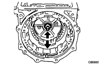
Push the output shaft with the power of 5 to 10 kgf.cm.
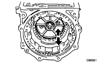
Pull on the overdrive support assembly with the power of 5 to 10 kgf.cm.
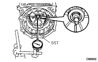
Using a SST and dial indicator, measure the end play of the input shaft. If the not end play is not as specified, even after reassembly, select another thrust bearing race.
- SST
- 09350-36010 (09350-06130)
- Standard:
0.3 to 0.7 mm (0.0118 to 0.0276 in.)
- Limit:
0.7 mm (0.0276 in.)
- HINT:
thrust bearing race thickness 35789-36100 0.85 to 0.95 mm (0.0335 to 0.03374 in.) 35789-36110 1.15 to 1.25 mm (0.0453 to 0.0492 in.) 35789-36120 1.45 to 1.55 mm (0.0571 to 0.061 in.) 35789-36130 1.75 to 1.85 mm (0.0689 to 0.0728 in.) 35789-36140 2.05 to 2.15 mm (0.0807 to 0.0846 in.)
Remove the 3 set bolts.
15.INSPECT OVERDRIVE DIRECT CLUTCH
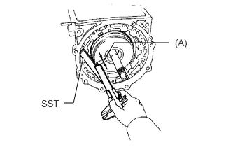
Using a SST and vernier caliper, measure the dimension (A) of the show in the illustration.
- SST
- 09350-36010 (09350-06090)
16.INSPECT PISTON STROKE OF OVERDRIVE DIRECT CLUTCH
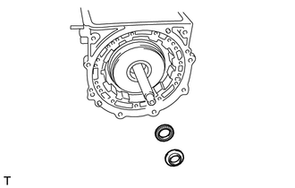
Coat the thrust needle roller bearing, the thrust bearing race with petroleum jelly.
Install the thrust needle roller bearing, the thrust bearing race.
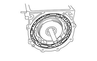
Install the front oil pump cover gasket.
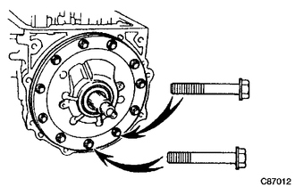
Install the oil pump assembly with the 11 bolts.
- Torque:
64 N*m (653 kgf*cm, 47 ft.*lbf)
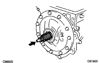
Push the input shaft with the power of 5 to 10 kgf.cm.
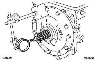
Set a dial indicator as show in the illustration.
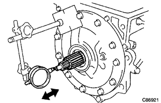
Using a SST and dial indicator, measure the end play of the input shaft. If the not end play is not as specified, even after reassembly, select another thrust bearing race.
- Standard:
0.4 to 0.9 mm (0.0157 to 0.0354 in.)
- Limit:
0.9mm
- HINT:
thrust bearing race thickness 35789-36040 0.76 to 0.81 mm (0.0299 to 0.0319 in.) 35789-36050 0.95 to 1.05 mm (0.0374 to 0.0413 in.) 35789-36060 1.35 to 1.45 mm (0.0531 to 0.0571 in.)
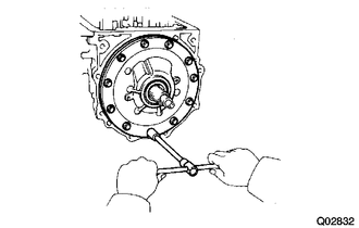
Remove the 11 bolts and oil pump assembly, front oil pump cover gasket from the transmission case.
Remove the thrust needle roller bearing, the thrust bearing race.