1HZ ENGINE MECHANICAL CYLINDER HEAD REASSEMBLY
CAUTION / NOTICE / HINT
Click hereEngine / Hybrid System>1HZ (ENGINE MECHANICAL)>CYLINDER HEAD>COMPONENTS
- NOTICE:
- ·
Thoroughly clean all parts to be assembled.
·Before installing the parts, apply new engine oil to all sliding and rotating surfaces.
·Replace all gaskets and oil seals with new ones.
PROCEDURE

 1.INSTALL FRONT AND REAR ENGINE HANGERS
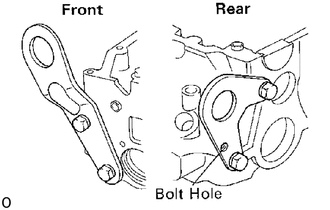
Install the engine hangers as shown in the illustration.
2.INSTALL HALF CIRCULAR PLUG
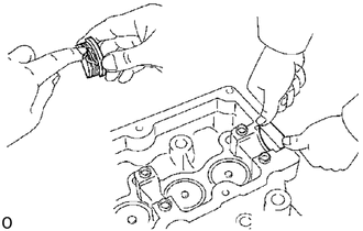
Remove any old packing (FIPG) material.
Apply seal packing to the half circular plug as shown.
- Seal packing:
Part No. 08826-00080 or equivalent
Install the half circular plug to the cylinder head.
3.SELECT COMBUSTION CHAMBER SHIM
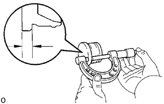
If using new combustion chamber:
Using a micrometer, measure the thickness of each used combustion chamber at the position shown in the illustration, then select the number of shims to be used.
| Combustion chamber thickness
mm (in.) |
No. of shims to be used |
|---|---|
| 6.02 - 6.05 (0.2370 - 0.2382) | 0 |
| 6.06 - 6.08 (0.2386 - 0.2394) | 1 |
| 6.09 - 6.11 (0.2398 - 0.2406) | 2 |
- Shim thickness:
0.03 mm (0.0012 in.)
- NOTICE:
-
If combustion chamber shims were already being used, do not perform the above step; use the same number of shims as were used before.
If reusing combustion chamber:
Install the combustion chamber back in the same position it was originally at.
4.INSTALL COMBUSTION CHAMBERS (1PZ and 1HZ)
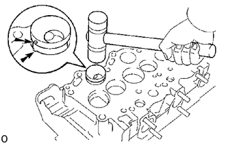
Align the knock pin of the combustion chamber with the notch of the cylinder head.
Using a plastic-faced hammer, tap in the (shim and) combustion chamber.
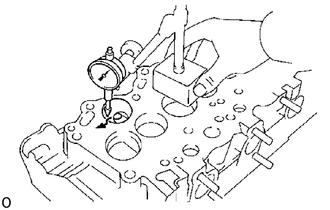
Using a dial indicator, measure the protrusion of the combustion chamber from the cylinder head.
- Protrusion:
Minus 0.04 - Plus 0.04 mm (Minus 0.0016 - Plus 0.0016 in.)
If the protrusion is less than specified, adjust with shims.
- Shim thickness:
0.03 mm (0.0012 in,)
If the protrusion is greater than specification, replace the chamber and recheck the protrusion.
5.INSTALL VALVES
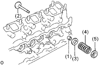
Install the following parts:
(1) Oil seal
(2) Valve
(3) Spring seat
(4) Valve spring
(5) Spring retainer
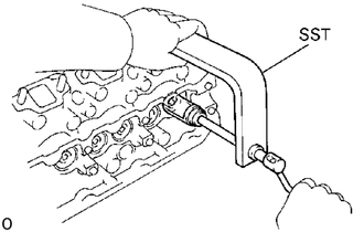
Using SST, compress the valve spring and place the two keepers around the valve stem.
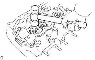
Using a plastic-faced hammer, lightly tap the valve stem tip to assure proper fit.
6.INSTALL VALVE LIFTERS AND SHIMS
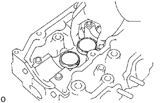
Check the valve lifter rotates smoothly by hand.