1HZ FUEL FUEL INJECTION PUMP REASSEMBLY
CAUTION / NOTICE / HINT
PROCEDURE

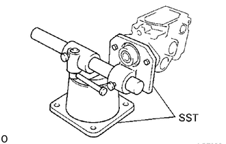
 1. PUMP BODY TO SST (STAND)
- SST
- 09241-76022 09245-54010
2.INSTALL FUEL INLET HOLLOW SCREW
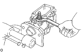
Install a new gasket and the hollow screw.
- Torque:
375 kg*cm (27 ft*lb, 37 N*m)
22180
3.INSTALL REGULATOR VALVE
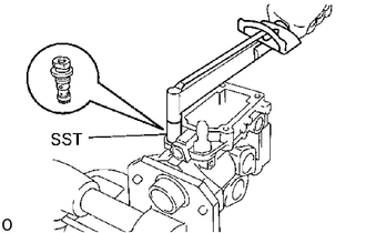
Install the two O-rings to the regulator valve.
Using SST, install the regulator valve.
- SST
- 09260-54012 (09262-54020)
- Torque:
90 kg*cm (78 in.*lb, 8.8 N*m)
22505
4.INSTALL FUEL FEED PUMP
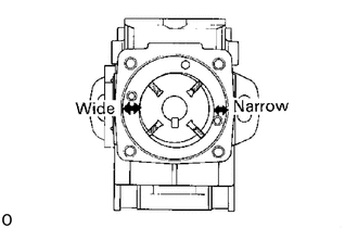
Install the liner, rotor and four blades.
Check that the liner and blades are facing in the correct direction, as shown.
Check that the blades move smoothly.
Align the fuel outlet holes of the cover and liner.
Install the pump cover with the two screws.
- Torque:
25 kg*cm (22 in.*lb, 2.5 N*m)
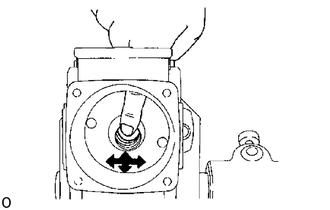
Check that the rotor moves smoothly.
5.INSTALL DRIVE SHAFT
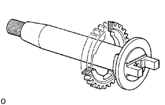
Install the drive gear on the drive shaft as shown.
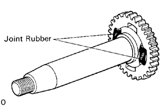
Install two new joint rubbers into the drive gear.
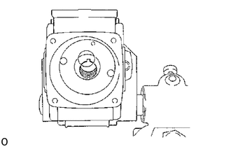
Position the key groove of the feed pump rotor upward.
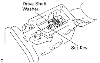
Install the set key and drive shaft washer on the drive shaft and insert the drive shaft assembly into the pump housing.
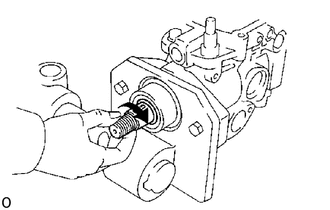
Check that the drive shaft turns without catching.
6.INSTALL TIMER PISTON
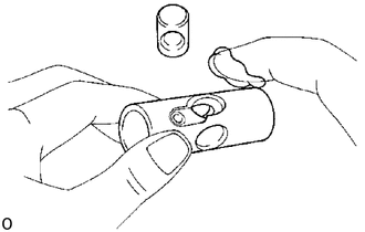
Apply No.50 DENSO grease to the timer piston.
Install the sub-piston into the timer piston.
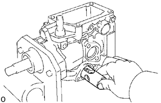
Insert the timer piston into the pump housing.
7.INSTALL ROLLER RING
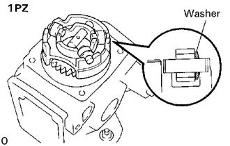
(1PZ)
Install the slide pin, three rollers and washers on the roller ring as shown in the illustration.
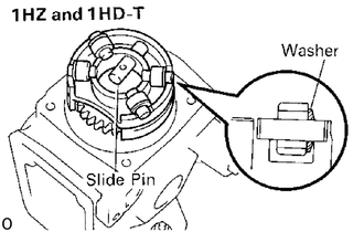
(1HZ and 1HD-T)
Install the slide pin, four rollers and washers on the roller ring.
Check that the roller is facing the flat surface of the washer.
Install the roller ring into the pump housing.
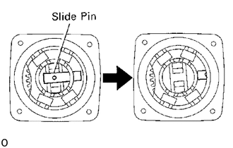
Carefully install the slide pin into the sub-piston.
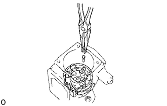
Install the stopper pin and clip.
8.INSTALL TIMER SPRING
Install a new O-ring to the timer adjusting screw.
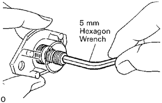
Using a 5 mm hexagon wrench, install the timer adjusting screw to the LH timer cover and temporarily install the nut.
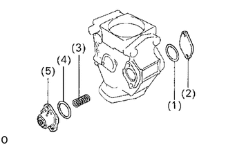
Install the following parts:
(1) New O-ring
(2) RH timer cover
(3) Timer spring
(4) New O-ring
(5) LH timer cover, timer adjusting screw and nut assembly
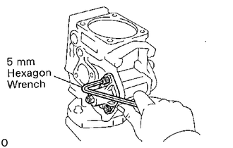
Using a 5 mm hexagon wrench, install the the four bolts.
9. PRESET TIMER ADJUSTING SCREW
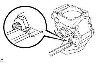
Using vernier calipers, measure the protrusion of the adjusting screw from the timer cover.
- Protrusion:
7.5 - 8.0 mm (0.295 - 0,315 in.)
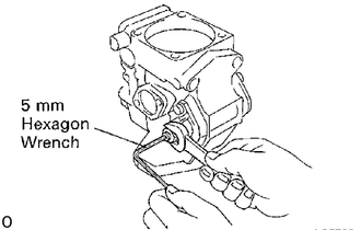
Using a 5 mm hexagon wrench, adjust the protrusion of the adjusting screw from the timer cover.
10.ADJUST PLUNGER SPRING SHIM
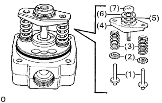
Install the following parts to the distributive head:
(1) Two plunger spring guides
(2) Two upper spring seats
(3) Two plunger springs
(4) Lower spring seat
(5) Upper plunger plate
(6) Lower plunger plate
(7) Pump plunger
- HINT:
-
Do not assemble the plunger spring shims at this time.
Using vernier calipers, measure clearance A indicated in the illustration.
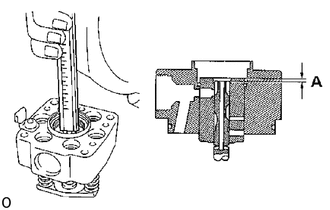
Determine the plunger spring shim size by using the following formula and chart.
1PZ and 1HZ
New plunger spring shim thickness = 5.8 - A
1HD-T
New plunger spring shim thickness = 5.1 - A
A ....Measured plunger position
| Measured clearance | Shim thickness | Measured clearance | Shim thickness |
|---|---|---|---|
| More than 5.3 (0.209) | 0.5 (0.020) | 4.3 - 4.5 (0.169 - 0.177) | 1.5 (0.059) |
| 5.0 - 5.2 (0.157 - 0.165) | 0.8 (0.031) | 4.0 - 4.2 (0.157 - 0.165) | 1.8 (0.071) |
| 4.8 - 4.9 (0.189 - 1.193) | 1.0 (0.039) | Less than 3.9 (0.154) | 2.0 (0.079) |
| 4.6 - 4.7 (0.181 - 0.185) | 1.2 (0.047) | - | - |
| Measured clearance | Shim thickness | Measured clearance | Shim thickness |
|---|---|---|---|
| More than 4.6 (0.181) | 0.5 (0.020) | 3.6 - 3.8 (0.142 - 0.150) | 1.5 (0.059) |
| 4.3 - 4.5 (0.169 - 0.177) | 0.8 (0.031) | 3.3 - 3.5 (0.130 - 0.138) | 1.8 (0.071) |
| 4.1 - 4.2 (0.161 - 0.165) | 1.0 (0.039) | Less than 3.2 (0.126) | 2.0 (0.079) |
| 3.9 - 4.0 (0.154 - 0.157) | 1.2 (0.047) | - | - |
- HINT:
- ·
For a measurement between listed sizes, use the next larger size. Ex. If thickness is 1.1 mm (0.043 in.) by calculation, use a 1.2 mm (0.047 in.) shim.
·Select two shims which have the same thickness.
11.ADJUST PLUNGER ADJUSTING SHIM (1PZ only)
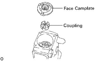
Install the coupling and face camplate.
- HINT:
-
Do not assemble the coupling spring.
Clean the plunger adjusting shim and contacting surface area.
Align the pin groove of the pump plunger with the face camplate pin.
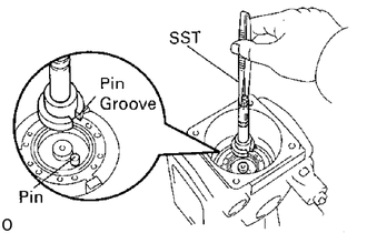
Using SST, install the used plunger adjusting shim and pump plunger.
- SST
- 09260-54012 (09269-54030)
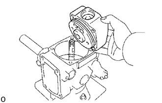
Install the distributive head with the four bolts.
- Torque:
120 kg*cm (9 ft*lb, 12 N*m)
- NOTICE:
-
Be careful not to damage the pump plunger.
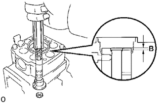
Using vernier calipers, measure dimension B indicated in the illustration.
Determine the plunger adjusting shim size by using the following formula and chart.
New adjusting shim thickness = T + (B - 3.3)
T ... Thickness of used shim
B ... Measured plunger position
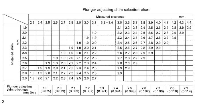
- EXAMPLE:
The 2.4 mm (0.094 in.) shim is installed and measured clearance is 3.7 mm (0.146 in.). Replace the 2.4 mm (0.094 in.) shim with a 2.8 mm (0.110 in.) shim.
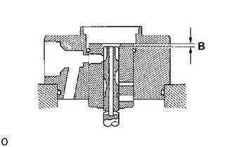
Install a new plunger adjusting shim and recheck dimension B.
- Dimension B:
3.2-3.4 mm (0.126-0.134 in.)
Remove the distributive head.
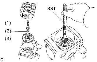
Using SST, remove the following parts:
(1) Pump plunger
(2) Plunger adjusting shim
(3) Face camplate
- SST
- 09260-54012 (09269-54030)
12.INSTALL COUPLING (1HZ and 1HD-T)
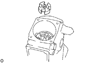
13.INSTALL FACE CAM PLATE
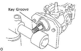
Face the drive shaft with the key groove facing upward.
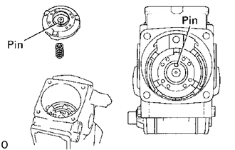
Install the coupling spring and camplate with the camplate pin facing the governor cover side.
14.INSTALL GOVERNOR LINK
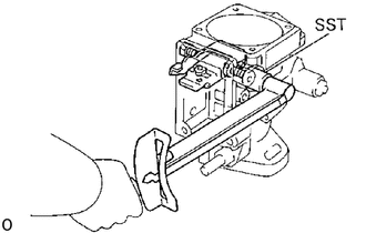
Using SST, install the governor link with two new gaskets and the two support bolts.
- Torque:
140 kg*cm (10 ft*lb, 14 N*m)
- SST
- 09260-54012 09269-54040
Check that the governor link moves smoothly.
15.INSTALL PUMP PLUNGER
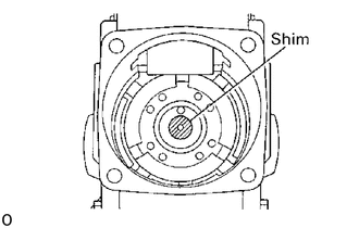
(1PZ)
Place the previously used plunger adjusting shim on center of the camplate.
(1HZ and 1HD-T)
Place the previously used plunger adjusting shim on the center of the camplate.
- NOTICE:
-
Do not apply grease to the shim.
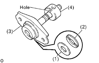
Install the following parts to the pump plunger:
(1) Lower plunger plate
(2) Upper plunger plate
(3) Lower spring seat
(4) Spill ring
- HINT:
-
Face the spill ring with the hole facing the lower spring seat.
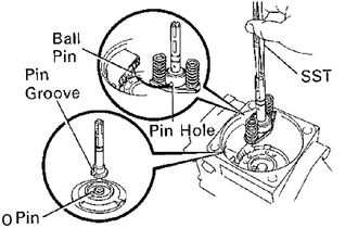
Align the pin groove of the plunger with the pin of the face camplate.
Align the ball pin of the governor link with the pin hole of the spill ring.
Using SST, install the pump plunger and two plunger springs.
- SST
- 09260-54012 (09269-54030)
16.INSTALL DISTRIBUTIVE HEAD
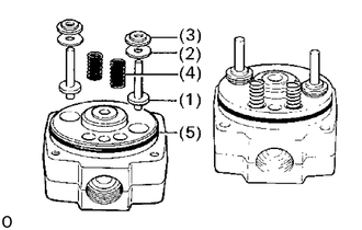
Apply No.50 DENSO grease to the following parts and install them to the distributive head:
(1) Two plunger spring guides
(2) Two new selected plunger spring shims
(3) Two upper spring seats
(4) Two lever support springs
(5) New O-ring
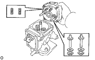
Install the distributive head.
- NOTICE:
-
Be careful not to damage the pump plunger.
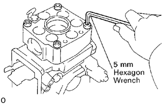
Using 5 mm hexagon wrench, install the four bolts.
- Torque:
120 kg*cm (9 ft*lb, 12 N*m)
- HINT:
-
Use the bolt which is 45 mm (1.77 in.) in length.
17.INSTALL DELIVERY VALVE HOLDERS
Install new gaskets and the valves into the distributive head.
Install the spring seats and springs into the delivery valve holders.
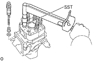
Using SST, install the delivery valve holders.
- SST
- 09260-54012 (09269-54020)
- Torque:
1PZ and 1HZ 500 kg*cm (36 ft*lb, 49 N*m)
1HD-T 550 kg*cm (40 ft*lb, 54 N*m)
22176
18.INSTALL DISTRIBUTIVE HEAD PLUG (1PZ only)
Install a new O-ring to the head plug.
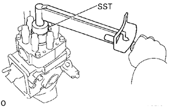
Using SST, install the head plug.
- SST
- 09260-54012 (09262-54010)
- Torque:
700 kg*cm (51 ft*lb, 69 N*m)
19.INSTALL GOVERNOR SHAFT AND FLYWEIGHT HOLDER
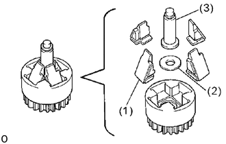
Install the following parts to the flyweight holder:
(1) Four flyweight
(2) No.2 flyweight washer
(3) Governor sleeve
- HINT:
-
Replace the four flyweights as a set.
Install a new O-ring to the governor shaft.
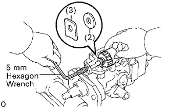
Place the flyweight holder assembly (1) in position, and install the No.1 flyweight washer (2) and governor gear adjusting washer (3) between the flyweight holder and pump housing.
Install the governor shaft through the governor gear adjusting washer, No.1 flyweight washer and flyweight holder assembly.
Using a 5 mm hexagon wrench, turn the governor shaft counterclockwise.
20.CHECK FLYWEIGHT HOLDER THRUST CLEARANCE
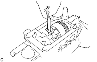
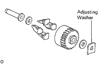
Using a thickness gauge, measure the thrust clearance between the housing pin and flyweight holder.
- Thrust clearance:
0.15 - 0.35 mm (0.0059 - 0.0138 in.)
If the thrust clearance is not as specified, adjust with a governor gear adjusting washer.
- Governor gear adjusting washer thickness:
1.05 mm (0.0413 in.)
1.25 mm (0,0492 in.)
1.45 mm (0.0571 in.)
1,65 mm (0,0650 in.)
1.85 mm (0.0728 in.)
21.ADJUST PROTRUSION OF GOVERNOR SHAFT
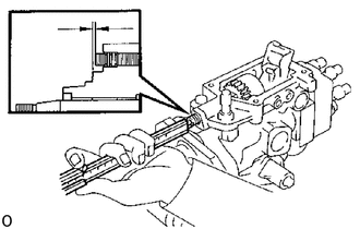
Using vernier calipers, measure the protrusion of the governor shaft.
- Protrusion:
0.5 - 2.0 mm (0.020 - 0.079 in.)
If the protrusion is not as specified, adjust by turning the governor shaft.
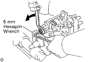
Install and tighten the nut while holding the governor shaft with a 5 mm hexagon wrench.
22. ASSEMBLE HIGH ALTITUDE COMPENSATOR (1PZ (w/ HAC) and 1HZ (w/ HAC))
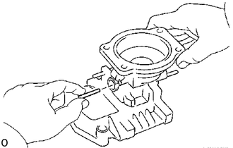
Install control lever
Insert the connecting pin into governor cover.
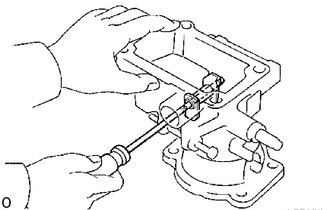
Using a small screwdriver, install the control lever with the support pin.
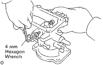
Using a 4 mm hexagon wrench, install two new gaskets and the two bolts.
23. ASSEMBLE BOOST COMPENSATOR (1HD-T)
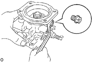
Install No.2 overflow screw
Install the No.2 overflow screw and cover.
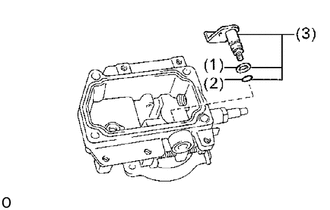
Install No.2 PCS lever
Install the following parts to the governor cover:
| (1) | Plate washer |
| (2) | O-ring |
| (3) | No.2 lever, O-ring and washer assembly |
Install control lever
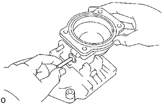
Insert the connecting pin into governor cover.
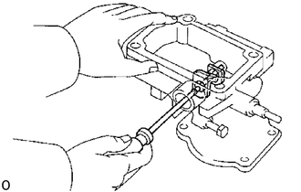
Using a small screwdriver, install the control lever with the support pin.
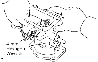
Using a 4 mm hexagon wrench, install two new gaskets and the two bolts.
24.INSTALL ADJUSTING LEVER SHAFT TO GOVERNOR SHAFT
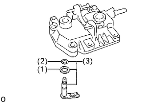
Install the following parts to the governor cover:
(1) Plate washer
(2) New O-ring
(3) Adjusting lever shaft, O-ring and plate washer assembly
22703A
25.INSTALL GOVERNOR COVER
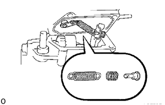
Install the speed control spring to the adjusting shaft.
Install a new gasket to the groove of the governor cover.
Install the damper spring and spring seat, and connect the speed control spring to the spring seat.
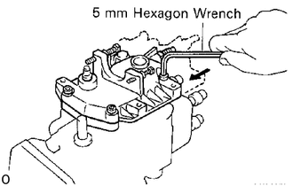
Using a 5 mm hexagon wrench, install the governor cover with the four bolts.
- Torque:
85 kg*cm (74 in.*lb, 8.3 N*m)
- HINT:
-
Use the bolt which is 35 mm (1.38 in.) in length.
(w/ HAC and 1HD-T)
Install the idle speed adjusting screw.
22701
26.INSTALL ADJUSTING LEVER
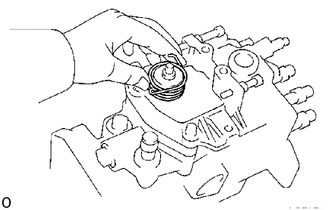
Place the return spring on the governor cover.
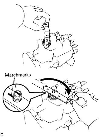
Hook the return spring to the adjusting lever, and turn and place the adjusting lever on the governor shaft.
Align the lines of the adjusting lever shaft and adjusting lever.
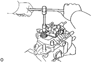
Install the adjusting lever with the spring guide and nut.
27.INSTALL PICKUP SENSOR (w/ TACHOMETER)
Install a new O-ring and pickup sensor.
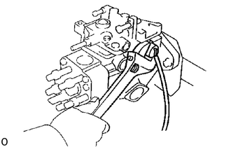
Connect the two lead wires to the connector.
- Torque:
210 kg*cm (15 ft*lb, 21 N*m)
28.ADJUST PLUNGER PRE-STROKE (1HZ and 1HD-T only)
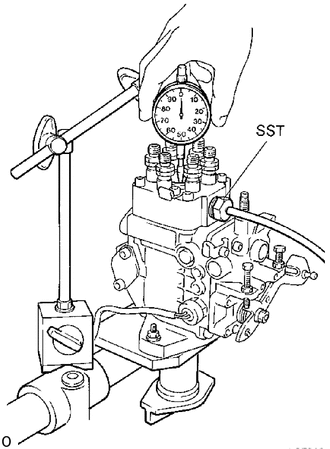
Install SST to the fuel cut solenoid installation screw section.
- SST
- 09275-17010
Set the dial indicator so that the tip of the dial indicator push rod touches the upper surface of the plunger.
Rotate the drive shaft, set the plunger to BDC and set the scale on the dial indicator to 0 mm (0 in.)
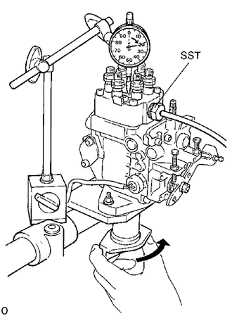
Apply a few drops of light oil (diesel fuel) to the top surface of the plunger, and when 0.1 kg/cm2 (1 .4 psi, 49 kPa) of air is applied to SST, bubbles appear on the upper surface of the plunger.
- SST
- 09275-17010
Slowly rotate the drive shaft in the pump rotation direction (clockwise) and read the dial indicator when the bubbles on the top of the plunger disappear.
- Pre-stroke:
0.15 - 0.25 mm (0.0059 - 0.0098 in.)
If the pre-stroke is not as specified, replace the plunger adjusting shim under the plunger with a different sized shim.
- Adjusting thim thickness:
mm (in.) 1.90 (0.0748) 2.35 (0.0925) 2.80 (0.1102) 1.95 (0.0768) 2.40 (0.0945) 2.85 (0.1122) 2.00 (0.0787) 2.45 (0.0965) 2.90 (0.1142) 2.05 (0.0807) 2.50 (0.0984) 2.94 (0.1157) 2.10 (0.0827) 2.55 (0.1004) 2.99 (0.1177) 2.15 (0.0846) 2.60 (0.1024) 3.04 (0.1197) 2.20 (0.0866) 2.65 (0.1043) 3.09 (0.1216) 2.25 (0.0886) 2.70 (0.1063) 3.14 (0.1236) 2.30 (0.0906) 2.75 (0.1083) 3.19(0.1256)
- HINT:
-
If the shim is made thicker, the pre-stroke is decreased
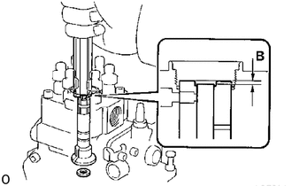
After completing the pre-stroke adjustment, check that dimension B is within specifications.
- Dimension B:
2.8 - 3.2 mm (0.110 - 0.126 in.)
If dimension B is not within the specification, replace the distributor head.
29.INSTALL DISTRIBUTIVE HEAD PLUG (1HZ and 1HD-T)
Install a new O-ring to the head plug.
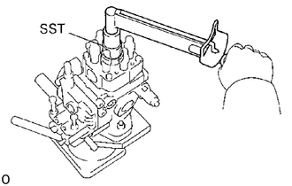
Using SST, install the head plug.
- SST
- 09260-54012 (09262-54010)
- Torque:
1HZ 700 kg*cm (51 ft*lb, 69 N*m)
1HD-T 900 kg*cm (65 ft*lb, 88 N*m)
30. ASSEMBLE HIGH ALTITUDE COMPENSATOR (1PZ (w/ HAC) and 1HZ (w/ HAC))
Install pneumatic bellows
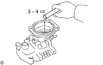
Insert 3 - 4 cc (0.18 - 0.24 cu in.) of engine oil into the bushing hole.
Place the following parts on the governor cover:
| (1) | Pneumatic bellows spring |
| (2) | Push rod |
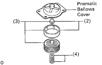
Install the following parts to the pneumatic bellows cover:
| (1) | Pneumatic bellows |
| (2) | Two rubber caps |
| (3) | Pneumatic bellows and two rubber caps assembly |
| (4) | Shims |
Install a new gasket and the pneumatic bellows and bellows cover assembly to the governor cover.
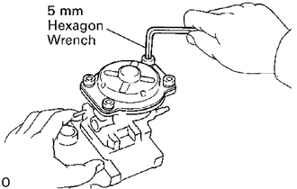
Using a 5 mm hexagon wrench, install the four bolts.
Install lever control spring
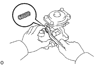
Install the lever control spring with a new gasket and the bolt.
31. ASSEMBLE BOOST COMPENSATOR (1HD-T)
Install guide bushing
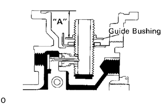
Install and adjust the guide bushing to the dimension "A" as shown in the illustration.
- Dimension "A":
Europe 19.2 - 19.3 mm (0.755 - 0.760 in.)
Others 18.6 - 18.7 mm (0.732 - 0.736 in.)
Install boost compensator diaphragm
Adjust boost compensator shim
Place the shim on the guide bushing
Using vernier calipers, measure the dimension "B" as shown in the illustration.
- Dimension "B":
Europe 4.8 - 5.0 mm (0.189 - 0.197 in.)
Others 6.0 - 6.2 mm (0.236 - 0.244 in.)
If the dimension is not within specification, select and install the correct shim.
- Adjusting shim thickness:
1.1 mm (0.043 in.)
1.3 mm (0.051 in.)
1.5 mm (0.059 in.)
1.7 mm (0.067 in.)
1.9 mm (0.075 in.)
2.1 mm (0.083 in.)
2.3 mm (0.090 in.)
2.5 mm (0.098 in.)
2.7 mm (0.106 in.)
2.9 mm (0.114 in.)
3.1 mm (0.122 in.)
3.3 mm (0.130 in.)
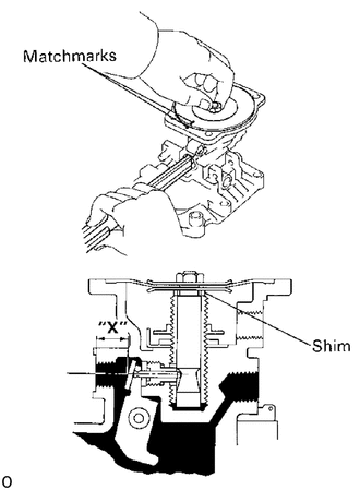
Adjust the installation direction of boost compensator diaphragm.
Install the shim and diaphragm.
- HINT:
-
Do not assemble the spring.
While pushing on the diaphragm, measure dimension "X" with vernier calipers as shown.
- Dimension "X":
6.9 - 7.1 mm (0.272 - 0.280 in.)
- HINT:
-
Measure at the center of the hole.
Place matchmarks on the diaphragm and governor cover.
Remove the diaphragm.
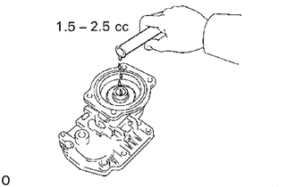
Insert 1.5 - 2.5 cc (0.09 - 0.15 cu in.) of engine oil into the bushing hole.
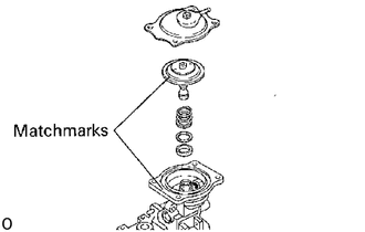
Install spring, shim and diaphragm.
Align the matchmarks on the diaphragm and governor cover.
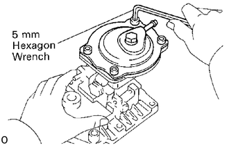
Using a 5 mm hexagon wrench, install the four bolts.
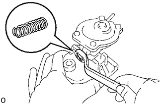
Install lever control spring
Install the lever control spring with a new gasket and the bolt.
22390A
32.INSTALL FUEL CUT SOLENOID
Install a new O-ring on the fuel cut solenoid.
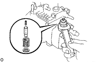
Install the strainer, valve, spring, a new gasket and the fuel cut solenoid.
- Torque:
225 kg*cm (16 ft*lb, 22 N*m)
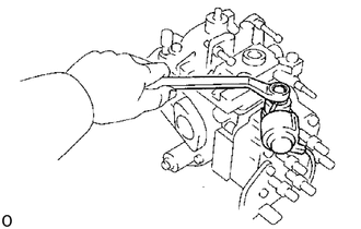
Install the lead wire to the fuel cut solenoid with the nut.
Install the dust cover to the fuel cut solenoid.
Install the lead wire connector to bracket.
33.INSTALL DASH POT (w/ Dash Pot)
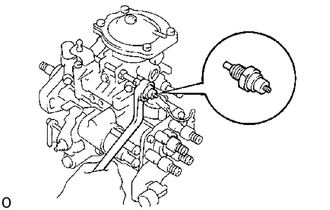
Install the dash pot and gasket.
34.INSTALL N0.1 PCS LEVER (w/ PCS)
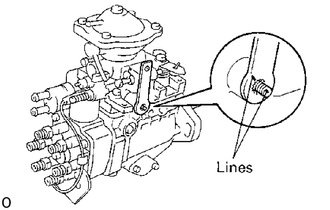
Align the lines of the levers.
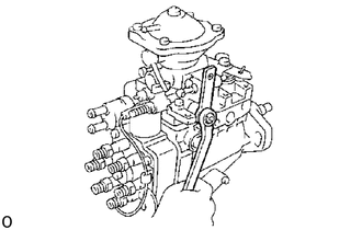
Install the nut.
35.INSTALL PCS ACTUATOR (w/ PCS)
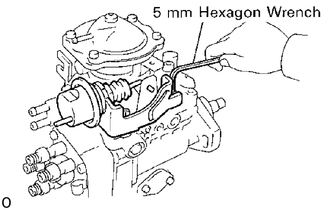
Using a 5 mm hexagon wrench, install the PCS actuator assembly with the two bolts.
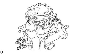
Install the clip.
Install the PCS adjusting screw.
36.INSTALL THERMO WAX (w/ ACSD)
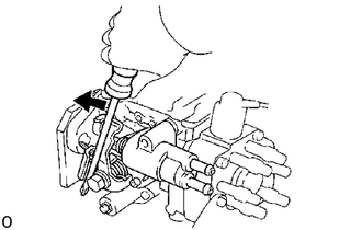
Using a screwdriver, turn the cold starting lever counterclockwise approx. 20°.
Put a metal plate (thickness of 3.5 - 7.5 mm (0.138 - 0.295 in.)) between the cold starting lever and thermo wax plunger.
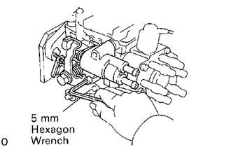
Install a new O-ring and the thermo wax with the two bolts.
37.INSTALL IDLE-UP LEVER (w/ ACSD)
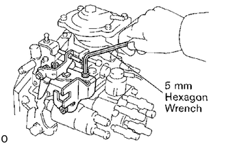
Using a 5 mm hexagon wrench, install the idle-up lever with the three bolts.
38.INSTALL IDLE-UP ACTUATOR (w/ A/C)
39.REMOVE INJECTION PUMP FROM SST (STAND)
- SST
- 09241-76022 09245-54010
40.PERFORM AIR TIGHT TEST
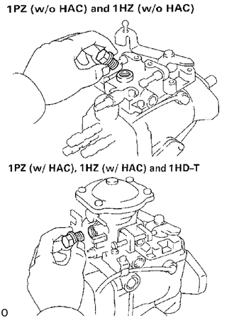
Install a bolt to the overflow port.
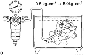
Connect an air hose to the fuel inlet pipe and place the injection pump into diesel fuel.
Apply 0.5 kg/cm2 (7 psi, 49 kPa) of pressure and confirm that there are no leaks.
Next check that there are no leaks with 5.0 kg/cm2 (71 psi, 490 kPa) of pressure applied.
41.SET KEY OF INJECTION PUMP DRIVE PULLEY ON DRIVE SHAFT