1HZ FUEL FUEL INJECTION PUMP INJECTION PUMP ADJUSTMENT
PROCEDURE

 1. PRE-SETTING OF LOAD SENSING TIMER
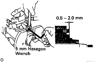
Using a 5 mm hexagon wrench, adjust the protrusion of the governor shaft.
- Protrusion:
0.5 - 2.0 mm (0.020 - 0.079 in.)
2.ADJUST TIMER
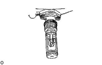
Set the timer measuring device at 0.
Apply 101 +/- 0.2 kPa (760 +/- 1.5 mm, 29.92 +/- 0.06 in.Hg) absolute pressure.
Measure the timer piston stroke at the below listed rpm.
| Pump rpm | Timer piston stroke mm (in.) |
|---|---|
| 800 | 0.43 - 1.43 (0.0169 - 0.0563) |
| 1,200 | 3.23 - 4.23 (1.1272 - 0.1665) |
| 1,600 | 5.09 - 6.09 (0.2004 - 0.2398) |
| 2,000 | 6.88 - 7.88 (0.2709 - 0.3102) |
| 2,500 | 6.68 - 7.88 (0.2709 - 0.3102)
(LST non-operation) |
- HINT:
-
Check that the hysteresis is within 0.3 mm (0.012 in.).
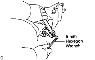
Using a 5 mm hexagon wrench, adjust by turning the timer adjusting screw.
- HINT:
-
Turn colckwise to reduce the stroke, turn counterclockwise to increase the stroke.
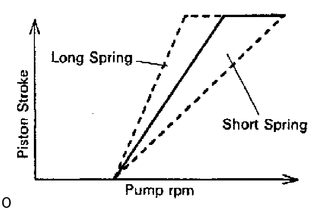
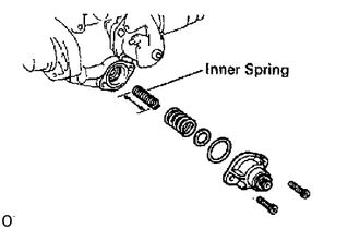
Check the timer stroke for characteristic tendency.
If tendency is not as specified, select and replace the inner spring.
- Timer spring free length:
32.0 mm (1.260 In.)
- HINT:
-
The timer stroke will increase with a long spring and decrease with a short spring.
3.CHECK INJECTION VOLUME
Apply 101 +/- 0.2 kPa (760 +/- 1.5 mm, 29.92 + 0.06 in.Hg) absolute pressure.
Measure the injection volume at each pump rpm.
| Item | Adjusting lever angle | Pump rpm | No. of measuring strokes | Injection volume cc (cu in.) |
|---|---|---|---|---|
| 1HZ | Plus 21-31° | 1,200 | 200 | 11.80 - 12.20 (0.72 - 0.74) |
If the injection volume at 100 rpm is not as specified, replace the governor sleeve plug as follows:
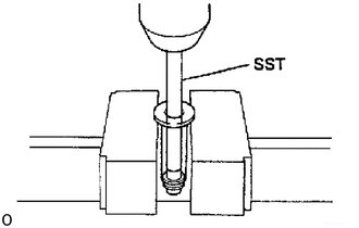
Using SST and a press, press out the sleeve plug assembly from the governor sleeve.
- SST
- 09236-00101 (09237-00070)
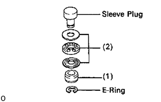
Remove the E-ring and following parts from the sleeve plug:
(1) Stop ring
(2) Bearing and 2 bearing retainers
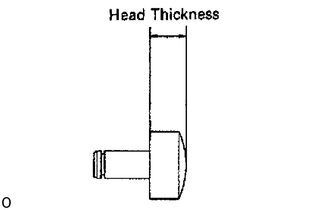
Measure the head thickness of the sleeve plug, and select a new sleeve plug.
- Governor sleeve plug head thickness:
mm (in,) 3.0 (0.118) 3.5 (0.138) 4.0 (0.158) 3.1 (0.122) 3.8 (0.142) 4.1 (0.161) 3.2 (0.126) 3.7 (0.148) 4.2 (0.166) 3.3 (0.130) 3.8 (0.150) - 3.4 (0.134) 3.9 (0.154) -
- HINT:
-
Lengthening the plug by 0.1 mm (0.004 in.) will decrease injection volume by 0.8 cc (0.05 cu in.).
-
If the variation limit is greater than specified, replace the delivery valve.
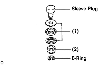
Install these parts to the new sleeve plug with a new E-ring:
(1) Bearing and 2 retainers
(2) Stop ring
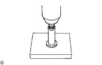
Using a press, press in the sleeve plug assembly to the governor sleeve.
4.ADJUST LOAD SENSING TIMER
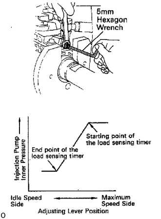
Using a 5 mm hexagon wrench, adjust the starting and end points of the load sensing timer by turning the governor shaft.
Set the adjusting lever to maximum position.
Apply 101 + 0.2 kPa (760 +/- 1.5 mm, 29.92 +/- 0.06 in.Hg) absolute pressure.
Measure the injection volume.
| Adjusting lever angle | Pump rpm | No. of measuring strokes |
|---|---|---|
| Maximum speed sidit | 1,600 | 200 |
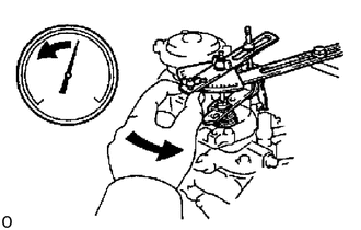
Slowly move the adjusting lever from the maximum speed side to the idle speed side, and secure it at the point where the pump inner pressure begins to drop.
Measure the injection volume at the drop point (starting point).
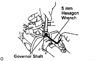
Using a 5 mm hexagon wrench, adjust the load sensing timer by turning the governor shaft, and perform the measurement again as specified.
- HINT:
-
The injection volume will increase approx. 3 cc (0.2 cu in.) with each 1/2 turn of the governor shaft.
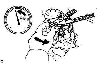
Check the end point injection volume by slowly moving the adjusting lever from the maximum speed side to the idle speed side, and secure it at the point where the pump inner pressure stops dropping.
| Pump rpm | No. of measuring strokes | Injection volume of each clinder cc (cu in.) |
|---|---|---|
| 1,600 | 200 | 8.2 (0.50) or more |
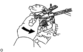
When the adjusting lever is moved slowly from the maximum speed side to the idle speed side, the timer stroke at the maximum retard angle (minimum timer piston stroke) should be as shown in the table below. (end point)
| Pump rpm | Timer piston stoke mm (in.) |
|---|---|
| 1,800 | 2.73 -3.73 (0.1075 -0.1469) |
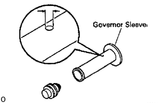
If the timer stroke is not as specified when the load sensing is at maximum retard angle, select a new governor sleeve.
- Governor sleeve hole diameter:
0.85 mm (0.0335 in.) x 2 holes
- HINT:
-
A large hole diameter decreases the timer stroke and a smaller hole diameter increases the timer stroke.
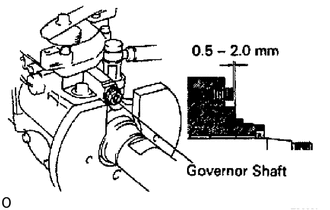
Check the protrusion of the governor shaft.
- Protrusion:
0.6 - 2.0 mm (0.020 - 0.079 in.)
5.ADJUST COLD STARTING SYSTEM
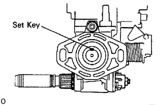
Remove the overflow screw and check the fuel temperature in the fuel pump.
- Fuel temperature:
15 - 35 °C (59 - 96 °F)
Set the set key of the pump drive shaft in a vertical or horizontal position.
Set the scale of the timer measuring device to 0.
Check the adjusting lever opening angle and consider this angle as 0.
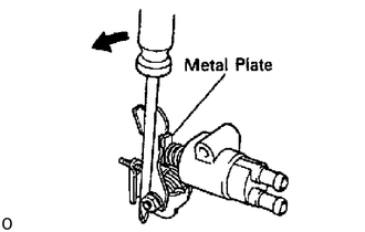
Remove the metal plate between the cold starting lever and thermo wax plunger.
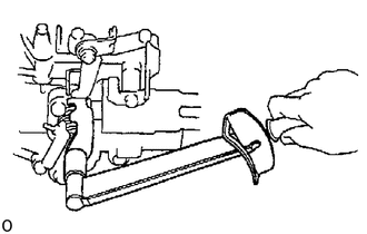
Torque the cold starting lever clockwise to approx. 4.9 N*m (50 kgf*cm, 43 in.* lbf) and keep the lever tightened for about 10 seconds. Then release the torque.
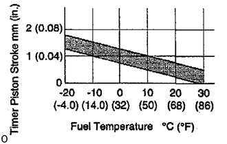
Measure the timer piston stroke.
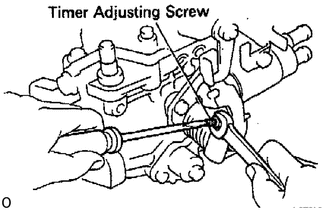
just by turning the timer adjusting screw.
- HINT:
-
Screw in for stroke decrease.