1HZ STARTING PRE-HEATING SYSTEM(for Super Glow Type) ON-VEHICLE INSPECTION
PROCEDURE

 1.INSPECT LIGHTING TIME OF GLOW INDICATOR LIGHT
Turn the ignition switch ON, and measure the lighting time.
- Light lighting time:
Refer to the chart graph
2.INSPECT AFTER GLOW
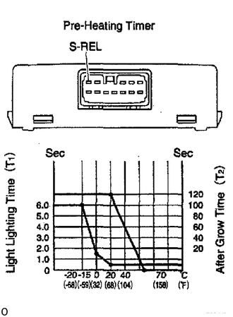
Turn the ignition switch ON, and measure the time battery voltage is applied to terminal S-REL of the pre-heating timer.
- After glow time:
Refer to the chart graph
3.DISCONNECT PRE-HEATING TIMER CONNECTOR
LOCATION: See relay locations in Electrical Wiring Diagram.
4.INSPECT PRE-HEATING TIMER CIRCUIT
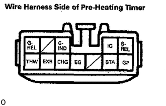
Check the connector on the wire harness side as shown in these chart:
| Check for | Tester connection | Condition | Specified value |
|---|---|---|---|
| Voltage | G-IND - Ground | Ignition switch OFF | No voltage |
| Ignition switch ON | Battery voltage | ||
| Voltage | IG - Ground | Ignition switch OFF | No voltage |
| Ignition switch ON | Battery voltage | ||
| Voltage | STA - Ground | Ignition switch OFF | No voltage |
| Ignition switch START | Battery voltage | ||
| Continuity | G-REL, S-REL - Ground | - | Continuity |
| Continuity | GP - Ground | - | Continuity |
| Continuity | THW - Ground | - | Continuity |
| Continuity | EG - Ground | - | Continuity |
5.RECONNECT PRE-HEATING TIMER CONNECTOR
6.REMOVE NO.1 GLOW PLUG RELAY
LOCATION: See relay locations in Electrical Wiring Diagram.
7.INSPECT NO.1 GLOW PLUG RELAY
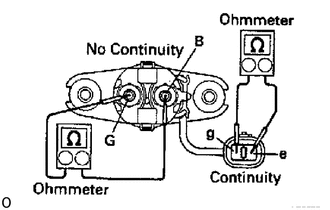
Inspect relay continuity
Using an ohmmeter, check that there is continuity between terminals e and g.
Check that there is no continuity between terminals B and G.
If continuity is not as specified, replace the relay.
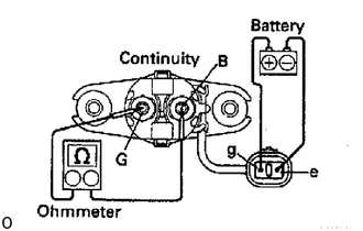
Inspect relay operation
Apply battery voltage across terminals e and g.
Using an ohmmeter, check that there is continuity between terminals B and G.
If operation is not as specified, replace the relay.
8.REINSTALL NO.1 GLOW PLUG RELAY
9.REMOVE NO.2 GLOW PLUG RELAY
LOCATION: See relay locations in Electrical Wiring Diagram.
10.INSPECT NO.2 GLOW PLUG RELAY
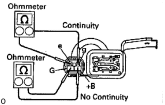
Inspect relay continuity
Using an ohmmeter, check that there is continuity between terminals e and g.
Check that there is no continuity between terminals B and G.
If continuity is not as specified, replace the relay.
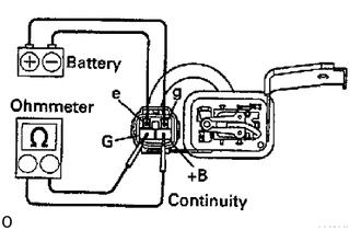
Inspect relay operation
Apply battery voltage across terminals e and g.
Using an ohmmeter, check that there is continuity between terminals B and G.
If operation is not as specified, replace the relay.
11.REINSTALL NO.2 GLOW PLUG RELAY
12.INSPECT GLOW PLUG RESISTOR
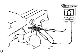
Using an ohmmeter, check that there is continuity between the glow plug resistor terminal and ground. If there is no continuity, replace the glow plug resistor.
- Torque:
34 N*m (350 kgf*cm, 25 ft*lbf)
13.REMOVE WATER TEMPERATURE SENSOR
LOCATION: In water outlet housing.
14.INSPECT WATER TEMPERATURE SENSOR
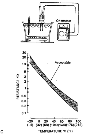
Using an ohmmeter, measure the n;isistance between the terminals.
- Resistance:
Refar to the chart graph
If the resistance is not as specified, replace the sensor.
15.REINSTALL WATER TEMPERATURE SENSOR
- Torque:
17.5 N*m (178 kgf*cm, 13 ft*lbf)
19850
16.INSPECT GLOW PLUGS
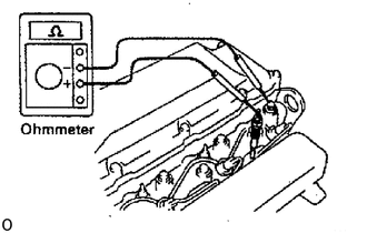
Using an ohmmeter, check that there is continuity between the glow plug terminal and ground.
If there is no continuity, replace the glow plug.
- Torque:
12.7 N*m (130 kgf*cm, 9.4 ft*lbf)
- NOTICE:
- ·
Be careful not to damage the glow plug pipes as it could cause an open circuit or shorten life of the glow plugs.
·Avoid getting oil and gasoline on the glow plug when cleaning.
·During inspection, be sure to wipe any oil off the terminal and bakelite washer with a dry cloth.
·Be careful not to apply more than 11 V (12 V type) or 22 V (24 V type) to the glow plug as it could cause an open circuit.