N04C-VL ENGINE MECHANICAL CYLINDER HEAD REASSEMBLY
PROCEDURE

 1.INSTALL STUD BOLT
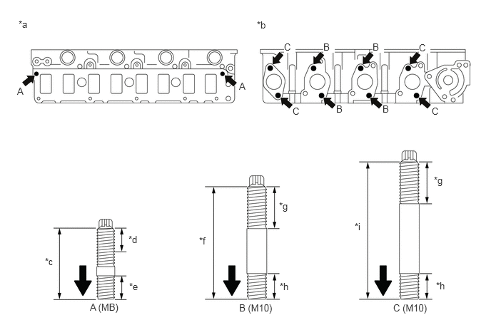
| *a | Intake Manifold Side | *b | Exhaust Manifold Side |
| *c | 32.5 mm (1.279 in.) | *d | 18.0 mm (0.708 in.) |
| *e | 10.5 mm (0.413 in.) | *f | 52.5 mm (2.066 in.) |
| *g | 19.5 mm (0.767 in.) | *h | 12.0 mm (0.472 in.) |
| *i | 63.5 mm (2.500 in.) | - | - |

|
Cylinder Head Side | - | - |
Using "TORX" socket wrenches E10 and E8, install the stud bolts.
2.INSTALL VALVE STEM OIL SHIELD
Install the valve to the cylinder head.
- NOTICE:
-
Attach the valve in order to guide the center of SST.
Apply a light coat of engine oil to the new valve guide bush.
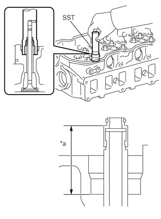
Using SST, install the new valve stem oil shield.
- SST
- 09201-E7010
- NOTICE:
- ·
After attaching the valve stem oil shield, check that there are no deformations, cracks, or slants to the rubber sections.
·After attaching the valve stem oil shield, check that the valve stem oil shields are seated properly and that they are at a certain depth.
·If there are any foreign objects within the valve or valve guide, the valve stem oil shield will become damaged. Check for any soiling or foreign objects before inserting the valve.
After attaching, check the attachment height of the valve stem oil shield.
| *a | 29.0 to 29.5 mm (1.142 to 1.161 in.) |
13711
3.INSTALL INTAKE VALVE
Apply engine oil to the valve tip.
Install the intake valve to the cylinder head.
- NOTICE:
-
Install the parts in their original locations.
13715
4.INSTALL EXHAUST VALVE
Apply engine oil to the valve tip.
Install the exhaust valve to the cylinder head.
- NOTICE:
-
Install the parts in their original locations.
5.INSTALL INNER COMPRESSION SPRING
Install the inner compression spring.
- NOTICE:
-
Install the parts in their original locations.
6.INSTALL VALVE SPRING RETAINER
Install the valve spring retainer.
- NOTICE:
-
Install the parts in their original locations.
13741A
7.INSTALL VALVE SPRING RETAINER LOCK
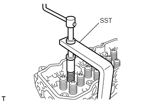
Using SST, compress the inner compression spring and place the 2 valve spring retainer locks around the valve stem oil shield.
- SST
- 09202-70020 09202-00021 (09202-01010, 09202-01020, 90154-80004)
- NOTICE:
- ·
Compress the valve spring making sure that the valve spring retainer does not come into contact with the valve stem oil shield.
· 2.198,0.552 2.479,1.063 false 1.385,0.646 1,1.229 1,1.229 1.938,0.646 false 0.854,1.198 1.167,1.396 0.313,0.198 10 false *a 2.438,1.094 2.75,1.292 0.313,0.198 10 false *b
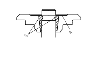
Check that the upper surfaces of the 2 valve spring retainer locks are in line and that they are flush with concave surfaces of the valve spring retainer.
Text in Illustration *a Upper Side of the Valve Spring Retainer Lock *b Concave Side of the Valve Spring Retainer Lock
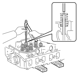
Using a pin punch 5, lightly tap the valve stem tip to ensure a proper fit.
- NOTICE:
-
Be careful not to damage the valve stem tip.