14B LUBRICATION OIL PUMP OIL PUMP INSPECTION
PROCEDURE

 1.INSPECT RELIEF VALVE
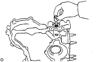
Coat the valve with engine oil and check that it falls smoothly into the valve hole by its own weight.
If it doesn't, replace the relief valve. If necessary, replace the oil pump assembly.
2.INSPECT DRIVE AND DRIVEN ROTORS
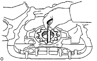
Inspect rotor tip clearance
Using a feeler gauge, measure the clearance between the drive and driven rotor tips.
- Standard tip clearance:
0.110 - 0.240 mm (0.0043 - 0.0094 in.)
- Maximum tip clearance:
0.30 mm (0.0118 in.)
If the tip clearance is greater than maximum, replace the rotors as a set.
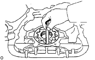
Inspect rotor body clearance
Using a feeler gauge, measure the clearance between the driven rotor and body.
- Standard body clearance:
0.144 - 0.229 mm (0.0035 - 0.0090 in.)
- Maximum body clearance:
0.40 mm (0.0157 in.)
If the body clearance is greater than maximum, replace the rotors as a set. If necessary, replace the oil pump assembly.
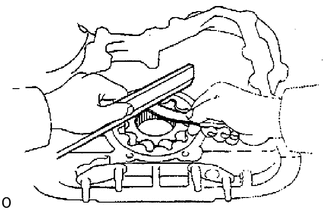
Inspect rotor side clearance
Using a feeler gauge and precision straight edge, measure the clearance between the rotors and precision straight edge.
- Standard side clearance:
0.036 - 0.090 mm (0.0014 - 0.0035 in.)
- Maximum side clearance:
0.15 mm (0.0059 in.)
If the side clearance is greater than maximum, replace the rotors as a set. If necessary, replace the oil pump assembly.
3.INSPECT DRIVE SPLINE
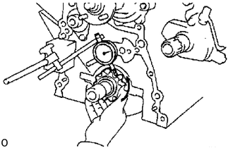
Using a dial indicator, measure the backlash while turning the drive rotor clockwise and counterclockwise in several places.
- Standard backlash:
0.541 - 0.790 mm (0.0213 - 0.0311 in.)
- Maximum backlash:
1.00 mm (0.0394 in.)
If the backlash is greater than maximum, replace the rotor and spline.