14B STARTING STARTER STARTER INSPECTION AND REPAIR
PROCEDURE

 1.INSPECT COMMUTATOR FOR OPEN CIRCUIT
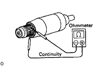
Using an ohmmeter, check that there is continuity between the segments of the commutator.
If there is no continuity between any segment, replace the armature.
2.INSPECT COMMUTATOR FOR GROUND
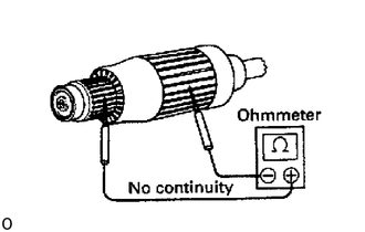
Using an ohmmeter, check that there is no continuity between the commutator and armature coil core.
If there is continuity, replace the armature.
3.INSPECT COMMUTATOR FOR DIRTY AND BURNT SURFACES
If the surface is dirty or burnt, correct it with sandpaper (No. 400) or on a lathe.
4.INSPECT COMMUTATOR CIRCLE RUNOUT
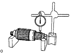
Place the commutator on V-blocks.
Using a dial gauge, measure the circle runout.
- Maximum circle runout:
0.05 mm (0.0020 in.)
If the circle runout is greater than maximum, correct it on a lathe.
5.INSPECT COMMUTATOR DIAMETER
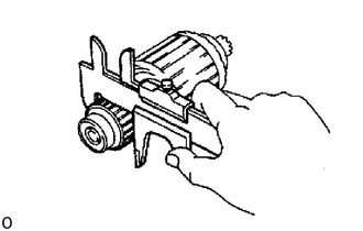
Using a vernier calipers, measure the commutator diameter.
- Standard diameter:
36 mm (1.42 in.)
- Minimum diameter:
35 mm (1.38 in.)
If the diameter is less than minimum, replace the armature.
6.INSPECT UNDERCUT DEPTH
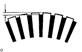
Check that the undercut depth is clean and free of foreign materials. Smooth out the edge.
- Standard undercut depth:
0.7 - 0.9 mm (0.028 - 0.035 in.)
- Minimum undercut depth:
0.2 mm (0.008 in.)
If the undercut depth is less than minimum, correct it with a hacksaw blade.
7.INSPECT FIELD COIL FOR OPEN CIRCUIT
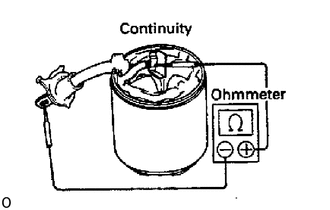
Using an ohmmeter, check that there is continuity between the lead wire and field coil brush lead.
If there is no continuity, replace the field frame.
8.INSPECT FIELD COIL FOR GROUND
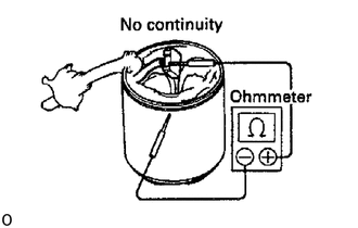
Using an ohmmeter, check that there is no continuity between the field coil end and field frame.
If there is continuity, repair or replace the field frame.
9.INSPECT BRUSH LENGTH
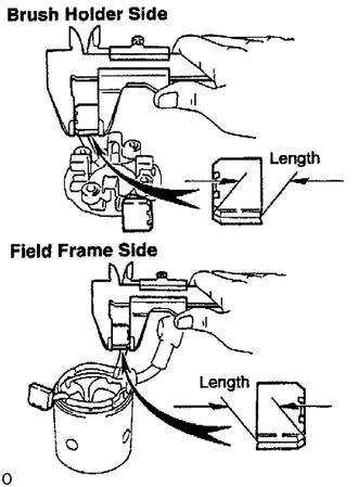
Using a vernier calipers, measure the brush length.
- Standard length:
20.5 - 21.0 mm (0.807 - 0.827 in.)
- Minimum length:
13.5 mm (0.531 in.)
If the length is less than minimum, replace the brush holder and field frame.
10.INSPECT BRUSH SPRING LOAD
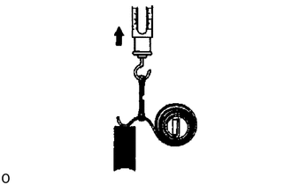
Take the pull scale reading the instant the brush spring separates from the brush.
- Spring installed load:
32 - 38 N (3.3 - 3.9 kgf, 7.3 - 8.5 lbf)
If the installed load is not within specification, replace the brush springs.
11.INSPECT BRUSH HOLDER INSULATION
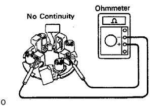
Using an ohmmeter, check that there is no continuity between the positive (+) and negative (-) brush holders.
If there is continuity, repair or replace the brush holder.
12.INSPECT GEAR TEETH
Check the gear teeth on the pinion gear, idle gear and clutch assembly for wear or damage.
If damaged, replace the gear or clutch assembly.
If damaged, also check the flywheel ring gear for wear or damage.
13.INSPECT CLUTCH PINION GEAR
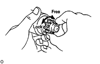
Hold the starter clutch and rotate the pinion gear clockwise, and check that it turns freely. Try to rotate the pinion gear counterclockwise and check that it locks.
If necessary, replace the clutch assembly.
14.INSPECT BEARINGS
Turn the bearing by hand while applying inward force.
If resistance is felt or the bearing sticks, replace the bearing.
15.IF NECESSARY, REPLACE FRONT BEARING
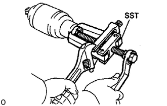
Using SST, remove the bearing.
- SST
- 09286-46011
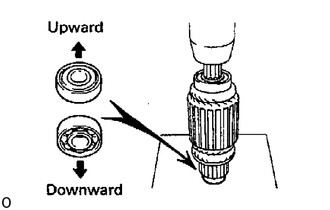
Using a press, press in a new bearing.
- NOTICE:
-
Be careful of the bearing installation direction.
16.IF NECESSARY, REPLACE REAR BEARING
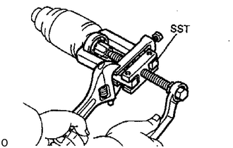
Using SST, remove the bearing.
- SST
- 09286-46011
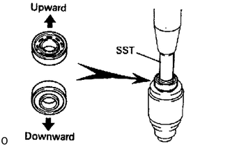
Using SST and a press, press in a new bearing.
- SST
- 09285-76010
- NOTICE:
-
Be careful of the bearing installation direction.
17.PERFORM PULL-IN COIL OPEN CIRCUIT TEST
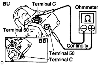
Using an ohmmeter, check that there is continuity between terminals 50 and C.
If there is no continuity, check and replace the magnetic switch.
18.PERFORM HOLD-IN COIL OPEN CIRCUIT TEST
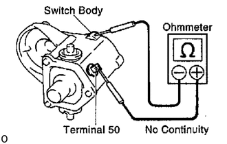
Using an ohmmeter, check that there is continuity between terminal 50 and the switch body.
If there is no continuity, replace the magnetic switch.