14B STARTING STARTER STARTER ASSEMBLY
CAUTION / NOTICE / HINT
- HINT:
-
Use high-temperature grease to lubricate the bearings and gears when assembling the starter.
PROCEDURE

 1.PLACE ARMATURE INTO FIELD FRAME
Apply grease to the armature bearings, and insert the armature into the field frame.
2.INSTALL BRUSH HOLDER
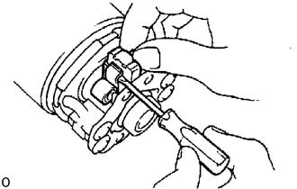
Place the brush holder on the armature.
Using a screwdriver, hold the brush spring back, and connect the brush into the brush holder. Connect the 4 brushes.
- NOTICE:
-
Check that the positive (+) lead wires are not grounded.
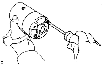
Install the end cover to the field frame with the 2 screws.
3.INSERT STEEL BALL INTO CLUTCH SHAFT HOLE
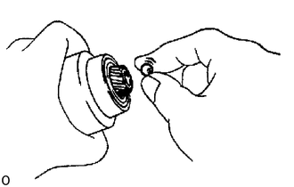
Apply grease to the steel ball.
Insert the steel ball into the clutch shaft hole.
4.INSTALL STARTER HOUSING, CLUTCH ASSEMBLY AND GEAR
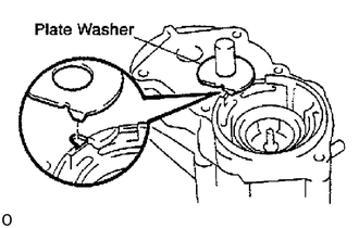
Place the plate washer in position on the magnetic switch assembly as shown in the illustration.
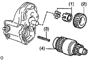
Place these parts in position on the magnetic switch assembly:
Bearing
Idler gear
Return spring
Clutch assembly
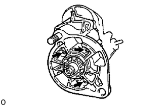
Assemble the starter housing and magnetic switch assembly and install the 3 screws.
5.INSTALL FIELD FRAME WITH ARMATURE TO MAGNETIC SWITCH ASSEMBLY
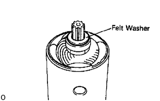
Place the felt washer in position on the armature shaft.
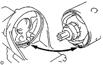
Align the protrusion of the field frame with the cutout of the magnetic switch.
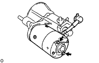
Install the field frame and armature assembly with the 2 through bolts.
- Torque:
9.3 N*m (95 kgf*cm, 82 in.*lbf)
Place the plate washer on terminal C, connect the lead wire to it and install the nut.
- Torque:
21 N*m (215 kgf*cm, 16 ft*lbf)
6.INSTALL LEAD WIRE
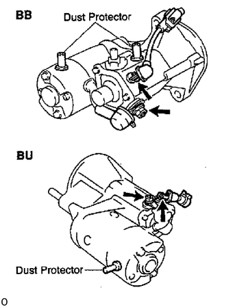
Install the lead wire to terminal 50 with the screw.
- Torque:
3.6 N*m (41 kgf*cm, 32 in.*lbf)
7.INSTALL DUST PROTECTOR