14B STARTING PRE-HEATING SYSTEM INTAKE HEATER RELAY INSPECTION
PROCEDURE

 1.REMOVE INTAKE HEATER RELAY (NO. 1 GLOW PLUG RELAY) (BB)
LOCATION: See relay locations in Electrical Wiring Diagram.
2.INSPECT INTAKE HEATER RELAY (NO. 1 GLOW PLUG RELAY) (BB)
Inspect relay continuity
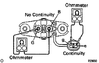
Using an ohmmeter, check that there is continuity between terminals e and g.
Check that there is no continuity between terminals B and G.
If continuity is not as specified, replace the relay.
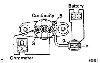
Inspect relay operation
Apply battery voltage across terminals e and g.
Using an ohmmeter, check that there is continuity between terminals B and G.
If operation is not as specified, replace the relay.
3.REINSTALL INTAKE HEATER RELAY (NO. 1 GLOW PLUG RELAY) (BB)
4.REMOVE INTAKE HEATER RELAY (BU111, 141)
LOCATION: See relay locations in Electrical Wiring Diagram.
5.INSPECT INTAKE HEATER RELAY (BU111, 141)
Inspect relay continuity
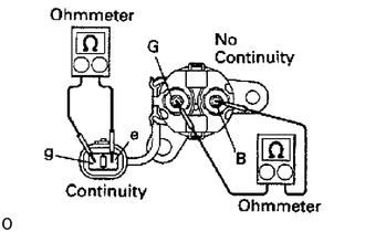
Using an ohmmeter, check that there is continuity between terminals e and g.
Check that there is no continuity between terminals B and G.
If continuity is not as specified, replace the relay.
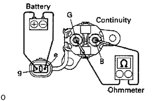
Inspect relay operation
Apply battery voltage across terminals e and g.
Using an ohmmeter, check that there is continuity between terminals B and G.
If operation is not as specified, replace the relay.
6.REINSTALL INTAKE HEATER RELAY (BU111, 141)
7.REMOVE INTAKE HEATER RELAY (BU211)
LOCATION: See relay locations in Electrical Wiring Diagram.
8.INSPECT INTAKE HEATER RELAY (BU211)
Inspect relay continuity
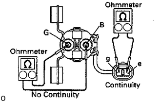
Using an ohmmeter, check that there is continuity between terminals e and g.
Check that there is no continuity between terminals B and G.
If continuity is not as specified, replace the relay.
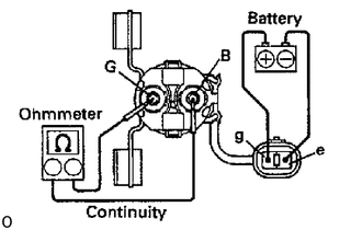
Inspect relay operation
Apply battery voltage across terminals e and g.
Using an ohmmeter, check that there is continuity between terminals B and G.
If operation is not as specified, replace the relay.
9.REINSTALL INTAKE HEATER RELAY (BU211)