N04C-UH ENGINE MECHANICAL ENGINE UNIT REASSEMBLY
PROCEDURE

 1.INSTALL CAMSHAFT BEARING SET
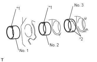
| *1 | Notch |
| *2 | Oil Hole |
Be sure to face the notches of the bearing No. 1 and No. 2 and oil holes of the No. 3 in the correct direction.
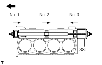
Using SST, install new camshaft bearings in the direction indicated by the arrow marks in the illustration.
- SST
- 09215-00101 (09215-00130, 09215-00141, 09215-00150, 09215-00161)
09215-00013 (09215-00021, 09215-00461)

|
Front |
- Journal Bearing Diameter:
Journal No. Inside Diameter Outside Diameter No. 1 57.0 mm (2.2441 in.) 60.0 mm (2.3622 in.) No. 2 56.8 mm (2.2362 in.) 59.8 mm (2.3543 in.) No. 3 56.6 mm (2.2283 in.) 59.6 mm (2.3465 in.)
- NOTICE:
-
Install the bearings No. 2, No. 1 and No. 3 in order.
13201A
2.INSTALL CONNECTING ROD SMALL END BUSH
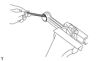
Uniformly chamfer one edge of the bush hole at the small end of the connecting rod.
- HINT:
- ·
Irregular chamfering can cause out-of-round of the bush, which may result in jamming during the insertion.
·Remove dust from the inner surface of the connecting rod hole.
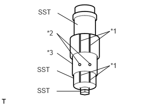
Mount the bush on the spindle.
- SST
- S0940-21470
S0948-11140
S9191-08252
| *1 | Groove |
| *2 | Oil Hole |
| *3 | Bush |
- Torque:
6.0 N*m (61 kgf*cm, 53 in.*lbf)
- HINT:
-
Align the oil holes in the bush with both grooves of the spindle and guide, and make sure that oil holes will meet with the oil path in the connecting rod leading from the big end bore in the rod.
Apply fresh engine oil around the bush and guide.
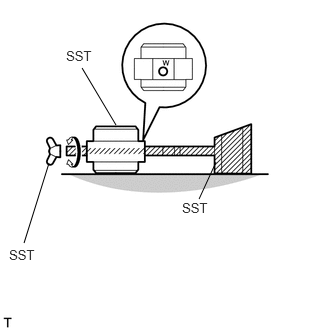
Prepare SST.
- SST
- S0940-21450
S0948-11130
S9233-10360
Assemble the guide and press sub-assembly by inserting its pin into the guide, then secure them with the wing nut.
- HINT:
-
Orient the letter W, stamped on the guide, above the pin.
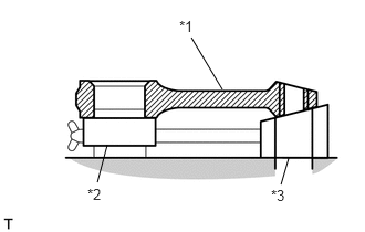
Align both supporting surfaces of the guide and press sub-assembly on an even plane.
| *1 | Connecting Rod |
| *2 | Guide |
| *3 | Press Sub-assembly |
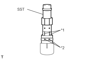
Install the bush into the connecting rod. Position the spindle and bush so that the oil holes align with the oil path through the connecting rod.
| *1 | Groove |
| *2 | Oil Hole |
- HINT:
-
Before installing, fully coat the connecting rod bore with fresh engine oil.
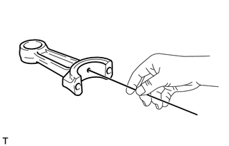
Inspect the bush position after the installation.
Make sure that the oil hole of the bush and the oil path of the connecting rod are suitably aligned allowing a 6 mm (0.236 in.) diameter rod to penetrate.
- HINT:
-
Misalignment can lead to insufficient lubrication, which may result in seizure.
With a new piston pin inserted in the piston, make sure that the pin can be rotated by hand without looseness.
13101A
3.INSTALL PISTON PIN HOLE SNAP RING
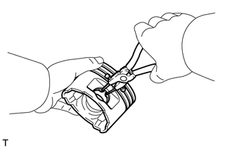
Using snap ring pliers, install a new snap ring into one side of the piston hole.
4.INSTALL PISTON
- HINT:
-
Before assembling the piston with the connecting rod, check whether the piston is specified for this engine. The check should be performed using the engine compatible identification code on the top of the piston.
- Engine compatible identification:
95
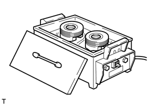
Assemble the piston and connecting rod.
Gradually heat the piston to approximately 50°C (122°F).
- CAUTION:
-
Do not touch the piston while it is hot.
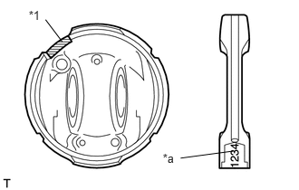
Coat the piston pin with engine oil.
| *1 | Notch |
| *a | Alignment Mark |
Install the piston onto the connecting rod with the notch on the piston facing in the same direction as the alignment mark on the rod. Then, secure them with the piston pin.
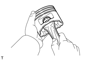
Check that the piston and piston pin fit securely.
- HINT:
-
Try to move the piston back and forth.
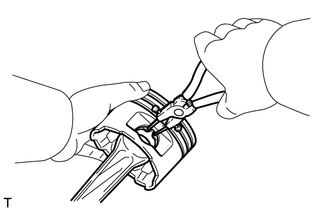
Using snap ring pliers, install a new snap ring into the other side of the piston pin hole.
13011
5.INSTALL PISTON RING SET
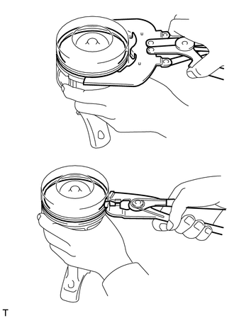
Face the identification marks on the piston ring up, then using a piston ring expander, install them in the following order of the oil ring, 2nd ring and 1st ring.
- HINT:
- ·
Never change the combination of the coil and oil ring.
·Connect the joint of the coil expander for the oil ring and install it inside the oil ring. Align the expander joint 180° opposite to the gap of the ring.
15708
6.INSTALL NO. 1 OIL NOZZLE SUB-ASSEMBLY
Install the No. 1 oil nozzle with the bolt.
- Torque:
29 N*m (291 kgf*cm, 21 ft.*lbf)
- NOTICE:
- ·
If the oil nozzle has been dropped or any impact has occurred to the nozzle, replace the nozzle with a new one.
·Replace a deformed nozzle with a new one.
15605
7.INSTALL OIL CHECK VALVE SUB-ASSEMBLY
Install a new gasket and the oil check valve with the bolt.
- Torque:
69 N*m (699 kgf*cm, 51 ft.*lbf)
11702
8.INSTALL CRANKSHAFT BEARING SET
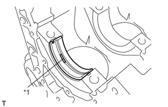
| *1 | Oil Hole |
Align the oil groove of the bearing with the oil hole of the cylinder block, and push in the 5 upper bearings.
- NOTICE:
-
Keep the back side of the bearing and the bearing surface free of foreign matter.
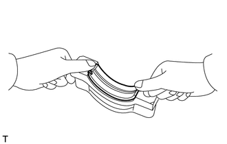
Align the bearing with the crankshaft bearing cap, and push in the 5 lower bearings.
- NOTICE:
-
Keep the back side of the bearing and the bearing surface free of foreign matter.
Install the crankshaft.
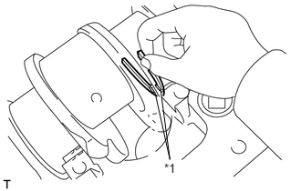
Insert the thrust washer into the clearance between the cylinder block and crankshaft with the oil groove facing outward.
| *1 | Groove |
Install the main bearing cap onto the cylinder block.
Apply a light coat of engine oil to the threads and under the cap bolt.
- NOTICE:
-
Be sure to install the removed thrust washer to its original position.
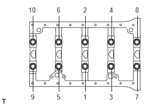
Temporarily tighten the bolts in several steps, in the sequence shown in the illustration.
Tighten the bolts to the specified torque.
- Torque:
60 N*m (612 kgf*cm, 44 ft.*lbf)
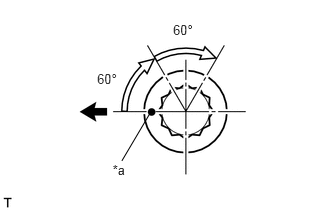
Mark the front of the bearing cap bolts with paint.
| *a | Paint Mark |
|
|
Front |
Retighten the bolts by 60° and then an additional 60° as shown in the illustration.
11462
9.INSTALL CYLINDER LINER
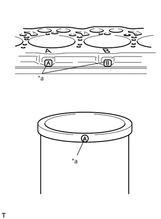
| *a | Position of Mark A, B or C |
- HINT:
- ·
When assembling the cylinder liner into the cylinder block, the clearance can be set to 3 levels.
·The upper surface and side surface of the cylinder block are stamped A, B or C. When using a new cylinder liner, insert a matching cylinder liner with the same symbol.
Apply engine oil to the cylinder block inside bore.
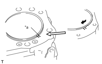
Align the marks of the cylinder liner and cylinder block.
| *a | Mark |
- HINT:
-
When reusing the cylinder liner, install it according to the marks made during the removal. When reusing the cylinder liner, misalignment with the cylinder block may concentrate stress on the thin part of the cylinder liner and it may break.
Install the cylinder liner.
- NOTICE:
-
Make sure to install the cylinder liner to its original location.
10.INSPECT PROTRUSION OF CYLINDER LINER
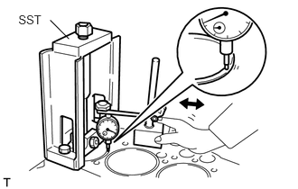
Mount SST onto the cylinder block.
- SST
- S0942-01460
Tighten the center bolt to the specified torque below to set the SST in the proper installation position.
- Torque:
9.8 N*m (100 kgf*cm, 7.2 ft.*lbf)
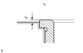
Using a dial gauge, measure the protrusion of the cylinder liner.
| *a | Pressure: 4903 N (500 kgf, 1100 lbf) |
| *b | Protrusion |
- Standard Protrusion:
0.01 to 0.08 mm (0.000394 to 0.00315 in.)
- Maximum Protrusion:
0.08 mm (0.00315 in.)
If the protrusion is greater than the maximum, replace the cylinder liner.
13202
11.INSTALL CONNECTING ROD BEARING
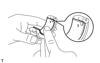
- NOTICE:
- ·
When reusing the bearing, reassemble the removed bearing as it was originally installed.
·Install the bearing with the oil hole onto the connecting rod side and install the bearing without the oil hole onto the cap side.
·Match the bearing protrusion with the notch of the connecting rod or cap.
·Keep the back side of the bearing and bearing surface of the bearing cap free of foreign matter.
12.INSTALL PISTON WITH CONNECTING ROD
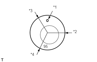
| *1 | Mark |
| *2 | Top Ring |
| *3 | 2nd Ring |
| *4 | Oil Ring |
- HINT:
-
Position the gaps of the piston rings at an even distance. Be careful not to position the gaps at the same position as the piston mark.
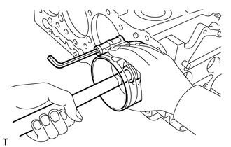
Using a piston ring compressor and a hammer handle, insert the piston with connecting rod assembly into the cylinder block.
- HINT:
- ·
Before the installation, apply engine oil to the piston pin, piston ring, cylinder liner and connecting rod bearing.
·Check the gap of each piston ring.
·Do not damage the inside of the liner.
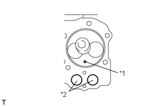
Make sure that the mark on the piston is on the tappet chamber side.
| *1 | Mark |
| *2 | Tappet Chamber |
Install the bearing cap onto the connecting rod with the front mark facing in the correct direction.
Uniformly install and tighten the bolts to the specified torque in several steps.
- Torque:
30 N*m (306 kgf*cm, 22 ft.*lbf)
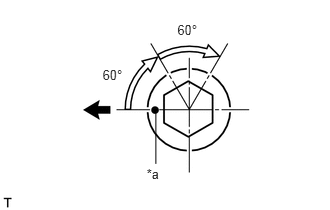
Mark the front side of the bolt head with paint as shown in the illustration.
| *a | Paint Mark |
|
|
Front |
Retighten the bolts by 60°.
Perform step (e) again.
Check that each painted mark is now at a 120° angle to the front.
11381A
13.INSTALL REAR ENGINE OIL SEAL
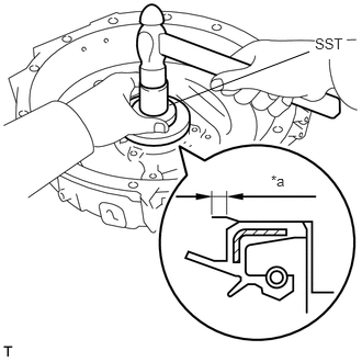
| *a | 4 mm (0.157 in.) |
Using SST and a hammer, tap in a new engine rear oil seal until it is 4 mm (0.157 in.) below the upper edge of the flywheel housing.
- SST
- 09223-78010
- NOTICE:
- ·
Be careful not to tap the oil seal at an angle.
·Keep the gap between the rear oil seal retainer edge and the oil seal free of foreign matter.
Apply MP grease to the oil seal lip.
11351
14.INSTALL FLYWHEEL HOUSING
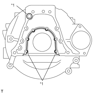
| *1 | Seal Packing |
Remove any old seal packing material from the contact surface.
Apply a continuous bead of seal packing (diameter: 1.5 to 2.5 mm (0.0591 to 0.0984 in)) as shown in the illustration.
- Seal packing:
Toyota Genuine Seal Packing Black, Three Bond 1207B or equivalent
- NOTICE:
- ·
Remove any oil from the contact surface.
·Install the flywheel housing within 3 minutes of applying the seal packing.
·Do not expose the seal packing to engine oil for at least 2 hours after installing.
Install the flywheel housing with the 14 bolts.
- Torque:
132 N*m (1346 kgf*cm, 97 ft.*lbf) for bolt (M14)
29 N*m (291 kgf*cm, 21 ft.*lbf) for bolt (M8)
13453
15.INSTALL FLYWHEEL RING GEAR
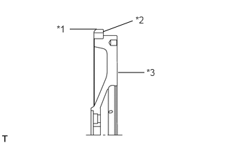
| *1 | Chamfer |
| *2 | Ring Gear |
| *3 | Flywheel |
Using a torch, heat the ring gear evenly to approximately 200°C (392°F).
- NOTICE:
-
Be careful not to overheat the ring gear.
Using a brass bar, strike the ring gear onto the flywheel with its chamfered gear teeth facing the block.
- Standard Clearance:
0.25 mm (0.00984 in.)
- NOTICE:
-
After installing, allow the ring gear to cool before handling.
13450A
16.INSTALL FLYWHEEL SUB-ASSEMBLY
Insert the flywheel slowly until it contacts the collar knock in order to prevent impact with the guide bar. Adjust the position, then insert it completely.
- NOTICE:
-
The flywheel is heavy. When installing, be careful not to drop it.
Apply clean engine oil to the threads of the flywheel bolts and the flywheel bolt seats.
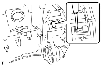
Insert a screwdriver through the inspection hole of the flywheel housing into the ring gear of the flywheel to keep it from turning together with the crankshaft.
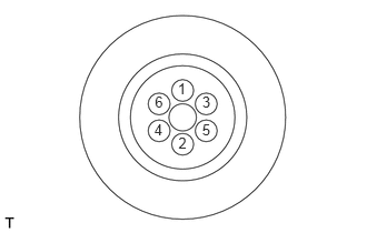
Tighten the flywheel bolts in several steps in the order shown in the illustration.
- Torque:
190 N*m (1937 kgf*cm, 140 ft.*lbf)
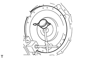
Using a dial indicator, measure the runout of the flywheel.
- Maximum Runout:
0.15 mm (0.00591 in.)
If the runout is greater than the maximum, resurface the sliding surface.
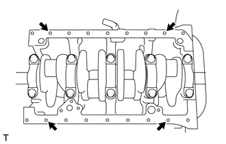
Temporarily install 4 bolts in the positions of the cylinder block shown in the illustration to prevent the wires from sliding toward the center of the block.
Attach 2 wires to the cylinder block.
- HINT:
-
The wires must be attached outside the installed bolts.
Using a chain block and an engine sling device, install the cylinder block onto the engine stand.
Remove the 4 bolts from the cylinder block.
11311H
17.INSTALL FRONT END PLATE
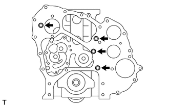
Install the front end plate with a new gasket and 4 bolts.
- Torque:
29 N*m (291 kgf*cm, 21 ft.*lbf)
Using a cutter, cut the gasket so that it is flush with the lower surface of the cylinder block.
15100
18.INSTALL OIL PUMP ASSEMBLY
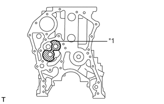
Apply engine oil to the oil pump case of the cylinder block and bearing.
| *1 | Engine Oil |
- NOTICE:
-
If engine oil is not applied, an oil suction malfunction will occur when starting the engine. The malfunction causes seizure or abnormal wear to the engine.
Install a new gasket and oil pump with the 7 bolts.
- Torque:
29 N*m (291 kgf*cm, 21 ft.*lbf)
Check that the oil pump rotates smoothly by hand after the installation.
19.INSTALL CRANKSHAFT TIMING GEAR OR SPROCKET
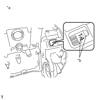
| *a | TDC of No. 1 and No. 4 Cylinder |
| *b | Matchmark |
Turn the crankshaft clockwise, and align the matchmarks of the flywheel and flywheel housing to set the No. 1 cylinder to TDC.
Align the set key on the crankshaft with the key groove of the crankshaft timing gear.
Using a hammer, tap in the crankshaft timing gear.
13508M
20.INSTALL NO. 1 IDLE GEAR SUB-ASSEMBLY
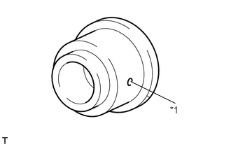
Install the idle gear and idle gear thrust plate onto the idle gear shaft.
| *1 | Oil Hole |
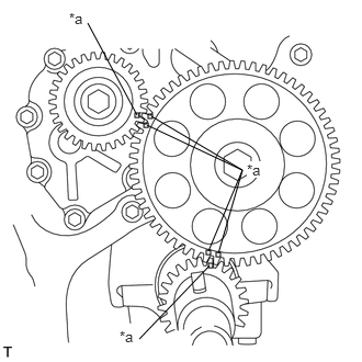
With the idle gear shaft oil hole facing down, match the alignment marks for each gear, and insert the shaft into the cylinder block.
| *a | Alignment Mark |
- NOTICE:
-
If the oil hole is not facing down, it causes burning or abnormal wear.
Tighten the bolt.
- Torque:
137 N*m (1397 kgf*cm, 101 ft.*lbf)
13501
21.INSTALL CAMSHAFT
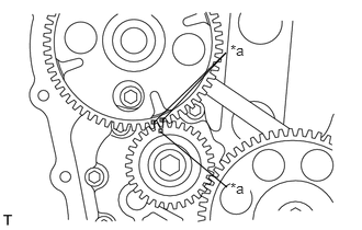
Apply engine oil to the camshaft journal and bearing.
Match the alignment marks of the camshaft timing gear and oil pump gear and install the camshaft.
| *a | Alignment Mark |
Install the thrust plate with the 2 bolts.
- Torque:
29 N*m (291 kgf*cm, 21 ft.*lbf)
13581C
22.INSTALL NO. 2 IDLE GEAR SHAFT
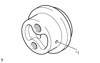
| *1 | Oil Hole |
Install the lock plate onto the end plate with the 3 bolts.
- Torque:
55 N*m (561 kgf*cm, 41 ft.*lbf)
Install a new O-ring onto the idle gear shaft.
With the idle gear shaft oil hole facing down, install the gear shaft onto the lock plate with the 2 bolts.
- Torque:
55 N*m (561 kgf*cm, 41 ft.*lbf)
- NOTICE:
-
If the oil hole is not facing down, it causes burning or abnormal wear.
13508N
23.INSTALL NO. 2 IDLE GEAR SUB-ASSEMBLY
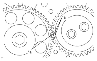
| *a | Alignment Mark |
Match the alignment marks of the No. 1 and No. 2 idle gears and install the No. 2 idle gear.
13572C
24.INSTALL NO. 2 IDLE GEAR THRUST PLATE
Install the thrust plate with the 2 bolts.
- Torque:
55 N*m (561 kgf*cm, 41 ft.*lbf)
11301C
25.INSTALL TIMING CHAIN OR BELT COVER OIL SEAL
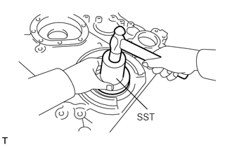
Using SST and a hammer, tap in a new oil seal to the timing gear case so that the oil seal is flush with the timing gear edge.
- SST
- 09223-78010
- NOTICE:
- ·
Be careful not to tap the oil seal at an angle.
·Keep the gap between the gear case edge and the oil seal free of foreign matter.
Apply MP grease to the oil seal lip.
26.INSTALL TIMING GEAR CASE
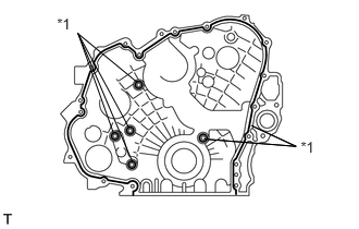
| *1 | Seal Packing |
Remove any oil packing material from the contact surface.
Apply a continuous bead of seal packing (diameter: 3 to 4 mm (0.118 to 0.157 in)) as shown in the illustration.
- Seal packing:
Toyota Genuine Seal Packing Black, Three Bond 1207B or equivalent
- NOTICE:
- ·
Remove any oil from the contact surface.
·Install the timing gear case within 3 minutes of applying the seal packing.
·Do not expose the seal packing to engine oil for at least 2 hours after installing.
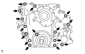
Install the timing gear case with the 15 bolts.
- Torque:
29 N*m (291 kgf*cm, 21 ft.*lbf)
13470
27.INSTALL CRANKSHAFT PULLEY ASSEMBLY
Install the pulley and spacer onto the crankshaft.
- HINT:
-
Align the pulley set key with the key groove of the pulley.
Using a 46 mm socket wrench, tighten the nut.
- Torque:
100 N*m (1020 kgf*cm, 74 ft.*lbf)
- HINT:
-
Insert a screwdriver through the inspection hole of the flywheel housing into the ring gear of the flywheel to keep it from turning together with the crankshaft.
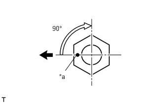
Mark the front side of the nut with paint as shown in the illustration.
| *a | Paint Mark |
|
|
Right Side of Engine |
Retighten the nut by 90°.
12270
28.INSTALL OIL SEPARATOR ASSEMBLY
Install 2 new O-rings onto the timing gear case.
Install the oil separator assembly with the 5 bolts.
- Torque:
55 N*m (561 kgf*cm, 41 ft.*lbf)
15104
29.INSTALL OIL STRAINER SUB-ASSEMBLY
Install a new O-ring onto the cylinder block.
Install the strainer with the 2 bolts.
- Torque:
29 N*m (291 kgf*cm, 21 ft.*lbf)
12101
30.INSTALL OIL PAN SUB-ASSEMBLY
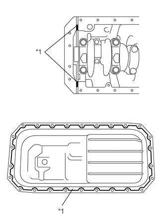
| *1 | Seal Packing |
Remove any old seal packing material from the contact surface.
Apply a continuous bead of seal packing (diameter: 3 to 4 mm (0.118 to 0.157 in.)) as shown in the illustration.
- Seal packing:
Toyota Genuine Seal Packing Black, Three Bond 1207B or equivalent
- NOTICE:
- ·
Remove any oil from the contact surface.
·Install the oil pan within 3 minutes of applying the seal packing.
·Do not expose the seal packing to engine oil for at least 2 hours after installing.
Install the oil pan with the 26 bolts.
- Torque:
29 N*m (291 kgf*cm, 21 ft.*lbf)
11351H
31.INSTALL FLYWHEEL HOUSING STAY RH
Install the stay with the 4 bolts.
- Torque:
132 N*m (1346 kgf*cm, 97 ft.*lbf) for bolt (M14)
97 N*m (990 kgf*cm, 72 ft.*lbf) for bolt (M12)
11351G
32.INSTALL FLYWHEEL HOUSING STAY LH
Install the stay with the 4 bolts.
- Torque:
132 N*m (1346 kgf*cm, 97 ft.*lbf) for bolt (M14)
97 N*m (990 kgf*cm, 72 ft.*lbf) for bolt (M12)
12311
33.INSTALL FRONT NO. 1 ENGINE MOUNTING BRACKET RH
Install the bracket with the 4 bolts.
- Torque:
69 N*m (699 kgf*cm, 51 ft.*lbf)
12315
34.INSTALL FRONT NO. 1 ENGINE MOUNTING BRACKET LH
Install the bracket with the 4 bolts.
- Torque:
69 N*m (699 kgf*cm, 51 ft.*lbf)
13751
35.INSTALL VALVE LIFTER
- NOTICE:
-
Be sure to install the removed push rod to its original position.
11101
36.INSTALL CYLINDER HEAD SUB-ASSEMBLY
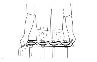
Install a new cylinder head gasket.
- NOTICE:
-
Always use a new cylinder head gasket after cleaning the surface of the cylinder head and cylinder block and keep them free of dirt, water and grease.
Install the cylinder head over the dowels on the cylinder block.
- HINT:
-
Since the cylinder head bolts are unique to this engine, do not substitute them with ordinary bolts.
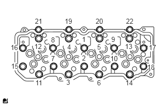
Uniformly install and tighten the cylinder head bolts (1 to 18) in several steps in the order shown in the illustration.
- Torque:
60 N*m (612 kgf*cm, 44 ft.*lbf)
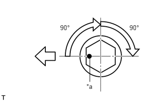
Mark the front side of each cylinder head bolt head with paint as shown in the illustration.
| *a | Paint Mark |

|
Front |
Retighten the cylinder head bolts by 90° in the same order as step (c).
Perform step (e) again.
Check that each painted mark is now at a 180° angle to the front.
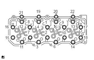
Uniformly install and tighten the cylinder head bolts (19 to 22) in several steps in the order shown in the illustration.
- Torque:
55 N*m (561 kgf*cm, 41 ft.*lbf)
13819
37.INSTALL VALVE BRIDGE
- NOTICE:
-
Be sure to install the removed bridge to its original location.
13781
38.INSTALL VALVE PUSH ROD
- NOTICE:
-
Be sure to install the removed push rod to its original location.
13901
39.INSTALL NO. 1 VALVE ROCKER SHAFT SUB-ASSEMBLY
Lubricate the rocker arm shaft and bush.
- NOTICE:
-
Confirm that the oil hole on the No. 1 valve rocker support aligns with the shaft oil hole. Improper installation will result in the entire valve being burned.
Install the No. 1valve rocker arms and No. 2 valve, No. 1 rocker supports and No. 2 and the valve rocker arm bushes onto No. 1 rocker shaft.
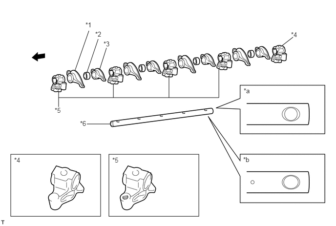
| *1 | No. 1 Valve Rocker Arm | *2 | Valve Rocker Arm Bush |
| *3 | No. 2 Valve Rocker Arm | *4 | No. 1 Valve Rocker Support |
| *5 | No. 2 Valve Rocker Support | *6 | No. 1 Valve Rocker Shaft |
| *a | Cylinder Head Cover Side | *b | Cylinder Head Side |
|
|
Front | - | - |
- NOTICE:
-
When installing, place the valve rocker shaft No. 1 with the smaller hole facing down.
Apply engine oil to the rocker arm and push rod.
Install the rocker shaft onto the cylinder head.
Install the bolts in the order shown in the illustration.
- Torque:
69 N*m (699 kgf*cm, 51 ft.*lbf)
- NOTICE:
-
Be careful that each push rod does not interfere with the adjusting screw.
40.ADJUST VALVE CLEARANCE
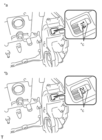
Turn the crankshaft clockwise to align the alignment marks on the flywheel with the line between the 2 numbers on the edge on the flywheel housing.
| *a | TDC of No. 1 and No. 4 Cylinder |
| *b | TDC of No. 2 and No. 3 Cylinder |
| *c | Alignment Marks |
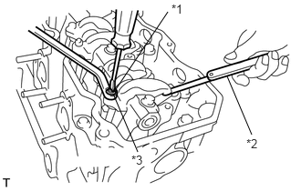
With the No. 1 piston positioned at TDC on the compression stroke, using a feeler gauge, adjust each valve clearance.
| *1 | Adjusting Screw |
| *2 | Feeler Gauge |
| *3 | Lock Nut |
- Valve Clearance (Cold):
Item Specified Condition Intake 0.30 mm (0.0118 in.) Exhaust 0.45 mm (0.0177 in.)
- HINT:
-
The feeler gauge should move with a very slight pull.
Loosen the lock nut on the valve rocker arm and loosen the adjusting screw.
Insert a 0.30 mm (0.0118 in.) feeler gauge for the intake or a 0.45 mm (0.0177 in.) feeler gauge for the exhaust between the adjusting screw on the valve rocker arm and the valve bridge.
Turn the adjusting screw on the valve rocker arm until the feeler gauge slides with a very slight drag, and lock the adjusting screw with the lock nut.
- Torque:
29 N*m (291 kgf*cm, 21 ft.*lbf)
Recheck the clearance.
Adjust the other valves.
Turn the crankshaft 1 revolution (360°) clockwise.
Adjust the valve clearance for each cylinder in the firing order.
- Firing order:
1 - 3 - 4 - 2
(The number of a cylinder is counted from the timing gear side)
11213
41.INSTALL CYLINDER HEAD COVER GASKET
Install a new cylinder head cover gasket onto the cylinder head cover.
11228
42.INSTALL CYLINDER HEAD COVER CUSHION
Install the 2 cylinder head cover spacers and 2 cylinder head cover cushions onto the cylinder head cover.
11201
43.INSTALL CYLINDER HEAD COVER SUB-ASSEMBLY
Install the cylinder head cover with the 2 bolts.
- Torque:
29 N*m (291 kgf*cm, 21 ft.*lbf)
11247
44.INSTALL CYLINDER HEAD COVER STAY
Install the 2 cylinder head cover stays onto the No. 2 cylinder head cover.
11202F
45.INSTALL CYLINDER HEAD COVER CUSHION RUBBER
Install the cylinder head cover cushion rubber onto the No. 2 cylinder head cover.
11202D
46.INSTALL NO. 2 CYLINDER HEAD COVER SUB-ASSEMBLY
Install the No. 2 cylinder head cover with the 2 bolts.
- Torque:
29 N*m (291 kgf*cm, 21 ft.*lbf)
12180E
47.INSTALL OIL FILLER CAP SUB-ASSEMBLY
Install the oil filler cap onto the No. 2 cylinder head cover.