N04C-UH EMISSION CONTROL EMISSION CONTROL SYSTEM ON-VEHICLE INSPECTION
CAUTION / NOTICE / HINT
- HINT:
-
In a malfunction where the EGR system is always on, black or white smoke may emit from the exhaust pipe.
PROCEDURE

 1.CHECK SEATING OF EGR VALVE
Start the engine. Check that the engine starts and then idles.
2.CHECK ENGINE CONDITION
Connect the intelligent tester to the DLC3.
Start the engine, then run it at idle.
Warm up the engine.
The coolant temperature should be between 75°C (167°F) and 90°C (194°F).
Turn the intelligent tester on.
Enter the following menus: Powertrain / Engine and ECT / Data List / EGR Position.
Check that the value of EGR position is within the specification.
- Standard:
Engine Condition EGR Valve Opening Position Expressed as Percentage If the result is not as specified, refer to the INSPECTION section.
During Idling 40 to 70 %
3.VISUALLY INSPECT HOSES, CONNECTORS AND GASKETS
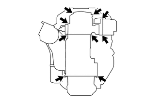
Check for cracks, leaks or damage.
Check the engine assembly to see if the portions indicated by the arrows have cracks, leaks or damage.
- NOTICE:
- ·
Detachment or other problems with the engine oil dipstick, filler cap, PCV hose and other components may cause the engine to run improperly.
·Air suction caused by disconnections, looseness or cracks in the parts of the air induction system between the throttle body and cylinder head will cause engine failure or engine malfunctions.
4.CLEAN CENTER EXHAUST PIPE ASSEMBLY
- HINT:
-
If the differential pressure across the DPF significantly exceeds the standard value when the engine is running at the maximum no load speed, a large amount of particulate matter may be deposited in the center exhaust pipe assembly. In such cases, clean the catalytic converter and monolithic converter by following the procedure below.
Remove the catalytic converter and the monolithic converter.
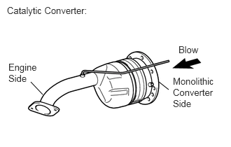
Clean the catalytic converter
Blow air into the catalytic converter with pipe assembly from the monolithic converter side to clean it.
- NOTICE:
-
To prevent particulate matter from scattering, vacuum it from the engine side by using a vacuum cleaner while blowing air.
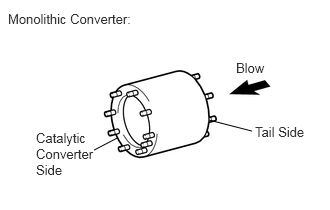
Clean the monolithic converter
Blow air into the monolithic converter from the tail side to clean it.
- NOTICE:
- ·
To prevent particulate matter from scattering, vacuum it by using a vacuum cleaner while blowing air.
·Thoroughly clean the converter by changing the blowing angle.
Reinstall the catalytic converter and the monolithic converter.
Conduct the forcible regeneration function.